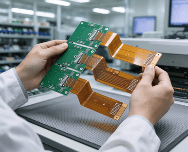






Typical Specification Range
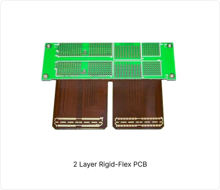
| Parameter | Typical Range |
|---|---|
| Layer count | 2 layers |
| Material type | Polyimide flex with selective FR4 rigid laminations |
| Surface finish | ENIG, OSP, Immersion Silver |
| Thickness | Rigid board thickness 0.3mm – 1.6mm, FPC Thickness 0.08mm – 0.2mm |
| Solder mask | Flexible solder mask and polyimide coverlay |
| Copper thickness | 0.5oz to 2oz |
| Special features | Selective bonding, stiffeners, controlled bend areas, ZIF fingers |
Manufacturing Process Insights
Lamination: FR4 rigid material is selectively bonded to polyimide flex core using no-flow prepreg. Precise registration and controlled pressure prevent wrinkles at transition zones.
Drilling and Plating: Mechanical drilling creates vias. Chemical copper deposition followed by electrolytic plating establishes interlayer connections. Plasma treatment improves hole wall adhesion.
Surface Finish and Coverlay: ENIG is applied for solderability. Polyimide coverlay protects flex circuits. Strict process sequencing minimizes thermal stress on flex material.
Risk Control: Cross-section inspection verifies bonding quality. CTE mismatch is managed through material selection and lamination profiles.
Manufacturing Order Profile
| Order Quantity | Order Proportion | Estimated Price Level | Typical Lead Time |
|---|---|---|---|
| Prototype (<=30 pcs) | 66% | From $215 | From 13 days |
| Small volume (30-200 pcs) | 19% | From $315 | From 15 days |
| Mass production (>200 pcs) | 15% | From $649 | From 16 days |
Manufacturing Challenges & Process Optimization
Transition Zone Delamination
Delamination occurs at rigid-flex junctions during thermal cycling or assembly.
CTE mismatch between FR4 and polyimide with insufficient resin flow creates weak bonds.
This defect lowers yield and causes intermittent opens that reduce product reliability.
Use stepped lamination with optimized pressure and temperature profiles.
Apply plasma treatment to flex surfaces before bonding.
Perform cross-section analysis on first articles to verify interface integrity.
Design Considerations
Define clear rigid and flex zones in planning. Maintain uniform dielectric thickness for impedance control. Minimize transition steps to improve manufacturability and reduce stress concentration.
Place plated through holes only in rigid sections. Avoid vias in flex bend areas. This reduces production risk and prevents copper cracking during repeated flexing.
Choose adhesive-less polyimide for improved flexibility and thermal performance. Balance bend endurance with cost. Material selection affects long-term reliability under thermal and mechanical stress.
ENIG offers excellent solderability for mixed assembly. It provides oxidation protection on exposed copper. This finish supports reliable multiple reflow cycles in production.