


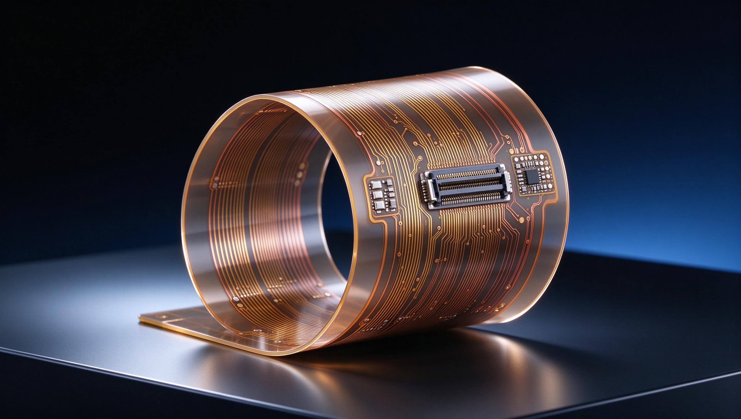
Flexible PCB

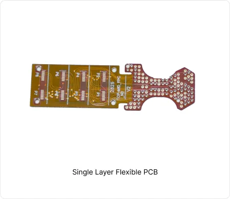
A Flexible PCB (Flex PCB / FPC) is a printed circuit board made with flexible polyimide substrates that can bend, fold, and twist without breaking. Unlike traditional rigid boards, it enables ultra-thin, lightweight, and three-dimensional designs that fit into tight spaces or moving parts.

This unique mechanical flexibility makes Flexible PCBs ideal for wearables, medical devices, foldable electronics, automotive sensors, and other applications where space, weight, and reliability are critical.

Item Technical Capability
Layers 1 – 16 layers
Maximum Board Size 250 × 1200 mm
Outline Tolerance Precision ±0.05 mm / Standard ±0.1 mm
FPC Board Thickness 0.1 – 0.32 mm
Coverlay Color Yellow / Black / White/ Transparant
Stiffener Material PI / Steel sheet / FR4 / Aluminum Sheet

Learn More About Capabilities

Flexible PCB Materials & Design Guides

  • FPC Materials & Manufacturing Guide
  • FPC Design Rules for Reliability
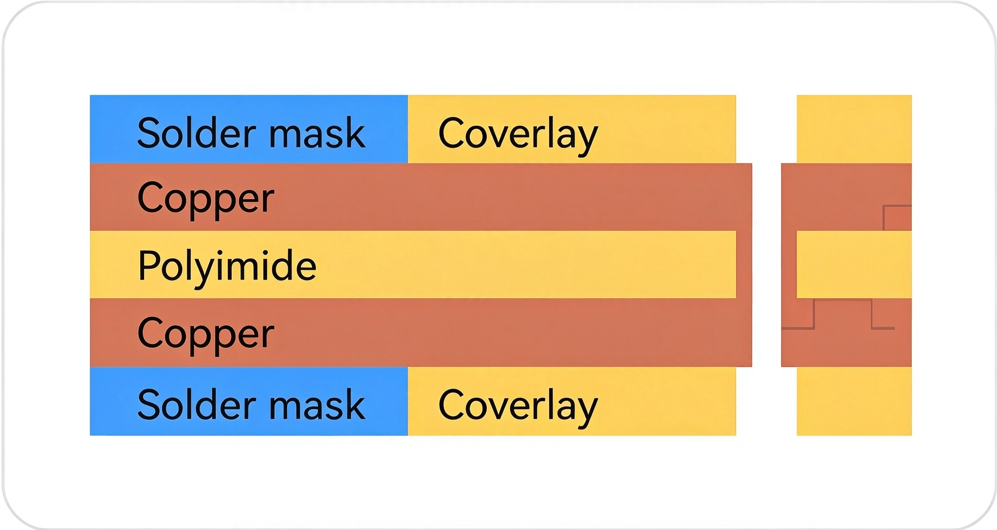
  • Material selectio directly determines flex life, signal integrity, and long-term reliability. Choosing the wrong substrate, copper type, or coverlay system is one of the most common root causes of field failures in flexible circuits. This guide gives you a clear engineering framework for making the right material and process decisions. √ Why polyimide remains the gold standard for high-reliability FPCs √ How RA vs ED copper fundamentally changes dynamic flex performance √ Coverlay and adhesive choices that prevent delamination

    √ Key manufacturing controls that protect yield and reliability

    Learn Flex PCB Material
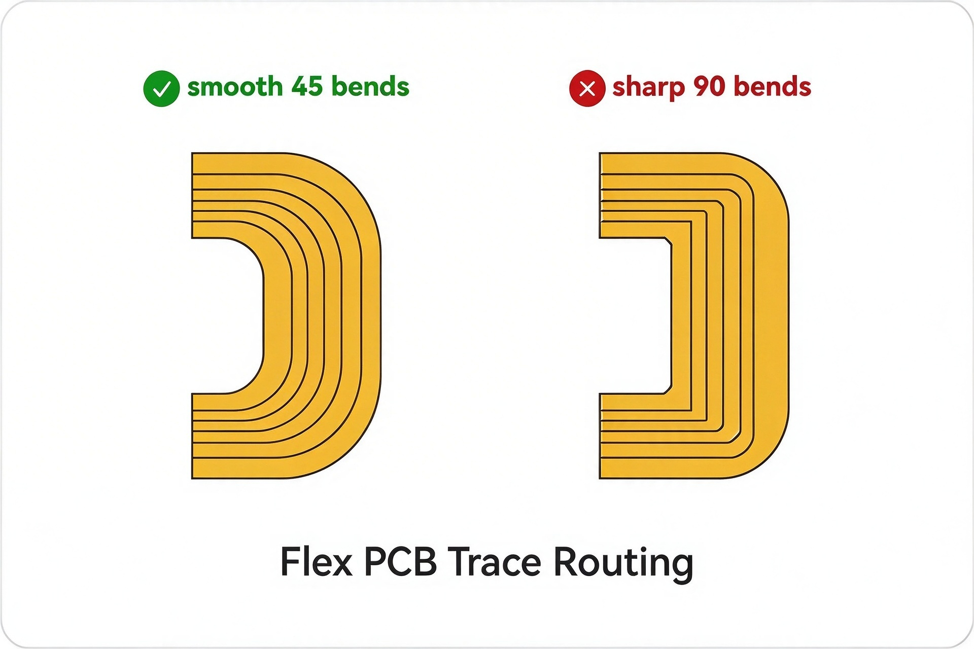
  • Most flexible PCB failures don’t come from manufacturing defects. They originate from design decisions that ignore mechanical stress, bend dynamics, and real production constraints. Good electrical design alone is not enough. This guide focuses on the practical rules that actually improve reliability and yield in production. √ Static vs dynamic flex: completely different design logic √ Bend region rules that prevent copper cracking √ Stack-up and via strategies that survive repeated flexing

    √ Common design mistakes that repeatedly show up in DFM reviews

    Learn Flex PCB Design Guide

Flexible PCB Manufacturing Insights

Custom FPC Fabrication Process


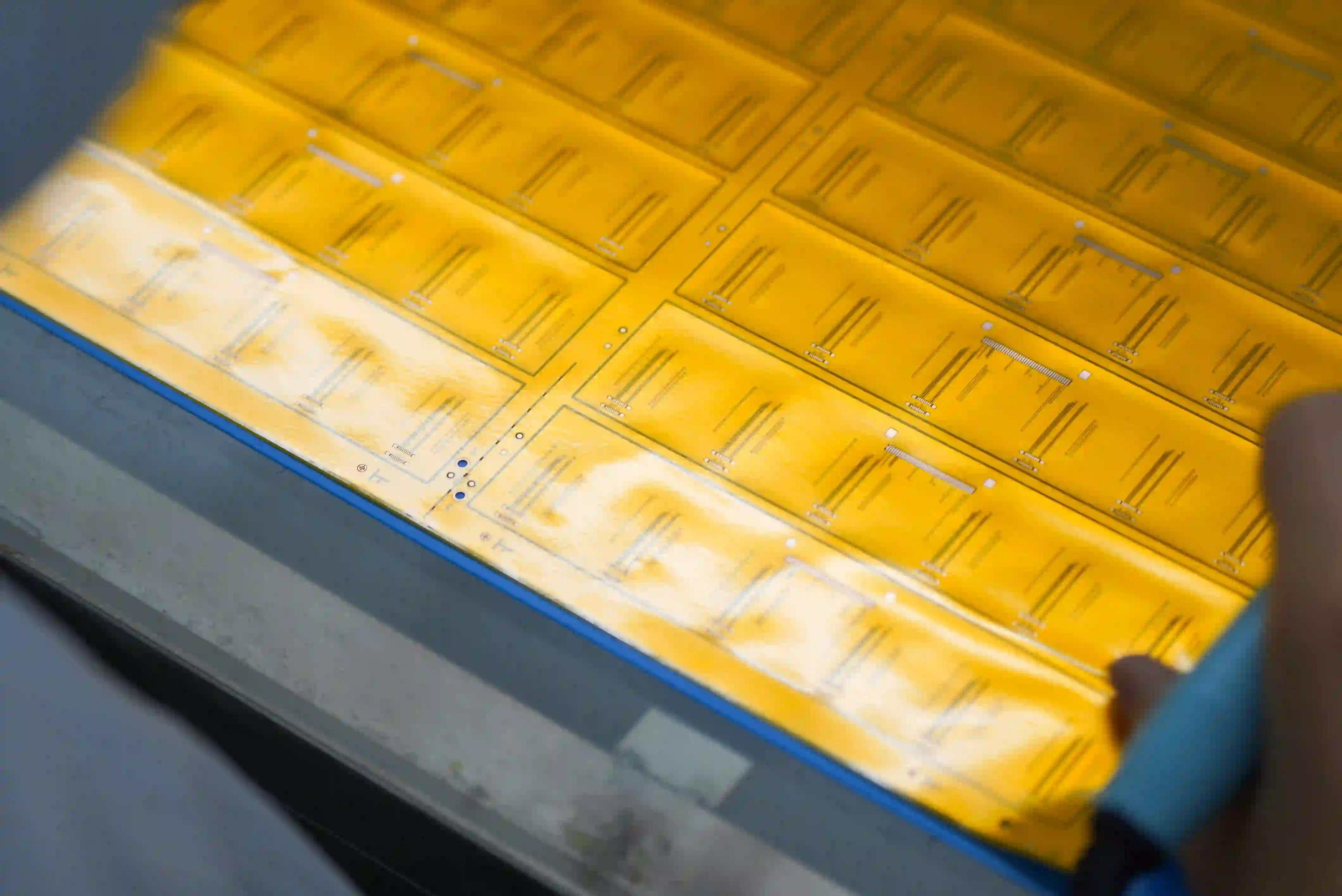
Flexible PCB manufacturing involves a series of processes that convert flexible materials into a finished circuit, including material preparation, drilling, circuit formation, coverlay lamination, surface finishing, testing, and final assembly. Each step affects the dimensional accuracy, electrical performance, flexibility, and reliability of the finished FPC. This guide explains the FPC manufacturing process step by step in CEZON's factory, including the purpose of each major process and the quality considerations involved.
At CEZON, FPC production is controlled throughout the manufacturing flow rather than relying only on final inspection. Material batches are verified before production, while critical parameters such as copper thickness, coverlay registration, curing conditions, and stiffener thickness are monitored at the corresponding process stages.

Flexible PCBs FAQs

Q1: What materials are used in flexible PCBs?
A1: Flexible PCBs typically use polyimide or polyester film as the base material, with copper foil for conductive layers and protective coverlays for insulation.
Q2: Does CEZON provide flexible PCB prototyping and PCB mass production?
A2: Yes. CEZON offers full-service flexible PCB solutions, including rapid prototyping, DFM review, small-batch runs, and large-scale mass production with strict quality control.
Q3: What is the minimum bend radius for flexible PCBs?
A3: The bend radius depends on thickness and layer count, typically 10 times the material thickness for single-layer boards to prevent cracking or delamination.
Q4: What is the difference between flexible PCB and rigid-flex PCB?
A4: The main difference is the board structure and application. Flexible PCBs are suitable when the circuit needs to remain flexible, while rigid-flex PCBs are useful when a design requires both rigid component mounting areas and flexible interconnections. Rigid-flex construction can also reduce connectors and separate cable assemblies in compact electronic products.
Q5: How does static flex differ from dynamic flex?
A5: Static flex and dynamic flex refer to how a flexible PCB is expected to bend during use. A static flexible PCB is designed to bend only a limited number of times, typically during installation or assembly, and then remain in a fixed position. A dynamic flexible PCB is designed for repeated bending or continuous flexing throughout its service life.

Get in Touch