


FPC Design Rules: The Complete Guide to Reliable Flexible PCB Design

Core Knowledge and Engineering Practices for FPC Design

Flexible printed circuits (FPCs) consist of thin, bendable substrates with conductive traces that enable compact, three-dimensional electronic packaging. Unlike rigid PCBs built on FR4 or similar laminates, FPCs use polymer films such as polyimide (PI) or polyester (PET) that allow repeated flexing or static forming. Key advantages include reduced weight and thickness, the ability to fit into tight or moving assemblies, and support for high-density interconnects without bulky connectors or cables. These characteristics make FPCs essential in space-constrained or motion-intensive applications.

Engineers distinguish between static bend and dynamic flex PCB applications. Static designs involve a one-time or occasional bend during assembly or installation, while dynamic flex requires repeated bending over the product lifetime, often tens of thousands to millions of cycles. The difference drives entirely different material and layout choices.

Industry demand comes from consumer electronics like foldable phones and smartwatches, automotive systems including dashboard displays and sensor harnesses, medical devices such as endoscopes and wearable monitors, aerospace avionics, and industrial automation. In each sector, poor FPC design leads to field failures, warranty claims, and delayed time-to-market.

This guide compiles practical design rules drawn from factory CAM experience, DFM reviews, and reliability testing. It covers material selection, bend region optimization, impedance control, application-specific considerations, and real production cases. Following these guidelines helps reduce defect rates, improve yields, and streamline RFQ processes for both designers and manufacturers.

Material Selection as the Foundation of FPC Design

Material selection is one of the earliest and most critical decisions in flexible circuit design. Unlike rigid PCBs, the mechanical performance, bend reliability, thermal resistance, and manufacturing cost of an FPC are heavily influenced by the material system chosen before layout begins. An inappropriate material choice can lead to premature fatigue failures, delamination, impedance instability, or assembly defects regardless of how well the circuit is routed.

Substrate Material Selection: PI vs PET

Property

Polyimide (PI)

Polyester (PET)

Temperature Resistance

Excellent (>300°C thermal stability)

Limited temperature resistance

Flexibility

Excellent

Good

Dimensional Stability

Excellent

Moderate

Reflow Soldering Compatibility

Suitable

Generally unsuitable

Reliability

High

Moderate

Typical Applications

Automotive, aerospace, industrial, medical electronics

Consumer electronics, low-cost products

Cost

Higher

Lower

Recommended For

High-reliability and demanding environments

Cost-sensitive static applications

PI remains the dominant substrate material for professional FPC designs because it combines thermal stability, mechanical durability, and long-term reliability. PET is primarily used when cost reduction outweighs performance requirements.

Polyimide is widely used in demanding flexible circuits because it offers good thermal stability, dimensional stability, and flexibility. It is suitable for applications that involve repeated bending, higher operating temperatures, or more demanding assembly processes.

Polyester, commonly known as PET, may be suitable for simpler and more cost-sensitive flexible circuits. It is often used in applications where the circuit has limited movement and does not need to withstand high-temperature processing.

The substrate should be selected according to the actual application rather than price alone. Designers should review operating temperature, bend requirements, dielectric performance, and assembly conditions before choosing the material.

Copper Foil Selection: RA vs ED Copper

Property

Rolled Annealed (RA) Copper

Electrodeposited (ED) Copper

Grain Structure

Horizontal elongated grains

Vertical columnar grains

Ductility

Excellent

Moderate

Dynamic Flex Performance

Excellent

Limited

Fatigue Resistance

High

Lower

Repeated Bend Cycles

Suitable

Not recommended

Static Flex Applications

Suitable

Suitable

Cost

Higher

Lower

Recommended For

Dynamic flex circuits and high-cycle bending

Static flex and cost-sensitive designs

Copper type is another important consideration in FPC design.

Dynamic flex circuits should generally use RA copper because its grain structure better withstands cyclic mechanical stress. While ED copper is widely used in static flex applications, repeated bending can accelerate fatigue cracking and reduce service life.

Designers must also evaluate whether to use adhesive-based or adhesiveless constructions. Adhesiveless laminates bond copper directly to the polyimide film, reducing overall thickness while improving thermal performance and bend life. These constructions are commonly recommended for high-density designs and dynamic flex regions. Adhesive-based materials remain widely used in cost-sensitive applications but typically exhibit lower long-term flex reliability.

Coverlay, Adhesive, and Stiffener Selection

Coverlay protects the copper traces and provides electrical insulation. Its thickness and opening design affect flexibility, bend performance, pad access, and assembly.

Adhesive-based and adhesiveless constructions may have different mechanical and dimensional characteristics. Designers should confirm which construction is suitable for the intended application.

Stiffeners are often added beneath connectors, component areas, or contact pads. They improve local support and help prevent damage during assembly or insertion. However, stiffeners also increase local thickness and may affect the bend transition.

In flexible PCB design, stiffeners should be placed only where mechanical reinforcement is needed. The transition between stiffened and flexible areas should be designed smoothly to avoid concentrated stress.

FPC Design Fundamental Rules

The main FPC design rules focus on controlling mechanical stress, protecting conductors, and maintaining manufacturable geometry. A flex circuit should not be treated as a rigid PCB that is simply made thinner.

Basic Layout Rules

Basic layout rules form the foundation of manufacturable and reliable FPC designs. Minimum trace width and spacing are typically 75 µm-100 µm for standard production volumes, with advanced processes supporting 50 µm or finer in prototype quantities. These limits depend heavily on copper thickness and chosen fabricator capabilities, so always confirm with your manufacturer rather than assuming generic values. In high-current areas, widen traces or use copper pours while maintaining flexibility; in signal layers, control impedance by adjusting width and reference plane distance.

Trace routing in flex areas should prioritize straight runs perpendicular to the bend axis to minimize strain. When perpendicular routing is impossible, use gentle arcs with radius at least 2× trace width. Stagger traces in differential pairs or multi-layer bundles to prevent overlapping stress points during repeated bending. Implement teardrops on all pads (minimum 50% extension) to strengthen the trace-pad junction and compensate for registration tolerances. All trace corners must use a minimum 45° chamfer or full radius — sharp 90° corners act as stress concentrators and frequently initiate copper cracks under dynamic flex.

Component pads in flex zones should be reinforced with local stiffeners, and keep large components or connectors away from bend areas. Proper Flexible PCB connector design is also important when the circuit uses an FPC ZIF connector, as interface selection, contact geometry, ZIF vs LIF requirements, and Gold finger design can all affect assembly reliability. Fiducials for assembly and inspection must be placed in rigid or semi-rigid zones with sufficient clearance. Panelization features such as mouse bites, stamp holes, or V-scores require careful positioning to avoid interfering with functional flexing areas. Following these rules consistently prevents common issues like trace fracturing, pad lifting, and registration-related defects during lamination and coverlay application.

Stack-up design principles

The stack-up determines the overall thickness, flexibility, electrical performance, and mechanical behavior of a flexible circuit. A suitable flexible PCB stack-up design should balance copper distribution, dielectric thickness, coverlay, adhesive, and reinforcement.

Single-layer flexible circuits are often used for simple routing, lightweight interconnects, and applications with limited electrical complexity. They generally provide good flexibility and can be easier to manufacture.

Double-layer flexible circuits provide more routing space and may support better grounding or signal distribution. However, the additional copper and dielectric layers increase total thickness and may reduce bend flexibility.


Multilayer flexible PCB design is useful when the circuit requires higher routing density, controlled impedance, shielding, or more complex interconnections.

However, additional layers increase the total thickness and can make the circuit less flexible. The stack-up should therefore be designed around the actual mechanical requirements.

Key principles include placing critical high-speed signals on inner layers when possible for better protection, using adhesiveless materials for thinner profiles and superior flex life, and carefully managing dielectric thicknesses for impedance targets. In rigid-flex designs, transition zones should gradually change layer count and stiffness with stepped or tapered copper removal to avoid abrupt stress changes that cause delamination.

Flexible PCB copper thickness selection follows a clear tradeoff: 12 µm or 18 µm for high-flex applications, 35 µm or heavier for power distribution. FPC copper thinning can help reduce bending strain in demanding flex areas, but the final design must still balance Flexible PCB trace width, current-carrying requirements, and copper thickness impedance. Total stack thickness in dynamic bend areas should stay below 0.15–0.25 mm for optimal performance. Always simulate the complete stack-up for both electrical (impedance, crosstalk) and mechanical (bend stress) performance. Unbalanced or overly thick stack-ups commonly cause warpage, coverlay wrinkling, or reduced flex endurance that only becomes evident after environmental testing.

Grounding and Shielding Strategies

Effective grounding and shielding are essential for maintaining signal integrity and EMI/EMC performance in FPC designs, particularly in high-speed or noise-sensitive applications. In flexible circuits, ground planes should be implemented as continuous copper pours on one or both sides of signal layers whenever possible, with strategic cross-hatching only when full planes would excessively reduce flexibility.

Solid ground planes provide the best return paths and shielding but increase stiffness; hatched patterns (typically 45-60% copper coverage) offer a compromise for dynamic flex zones while still controlling impedance and reducing crosstalk.

Stitching vias or conductive adhesive between ground layers in multilayer FPCs ensure low-impedance connections across the stack-up. In bend areas, avoid breaking ground continuity—route ground traces or planes to follow the neutral bend axis where mechanical strain is minimal.

For EMI shielding, consider additional silver ink shielding layers, copper foil tapes, or dedicated shield films bonded to the coverlay, especially in wearable and medical devices where external interference or patient safety is critical. Always verify shielding effectiveness through radiated emission testing and maintain ground return paths as short and wide as possible to minimize loop inductance. Poor grounding frequently leads to signal noise, radiated emissions failures, or ground bounce issues that only appear during system-level integration.

Via and Pad Design Guidelines

Via and pad design in FPCs requires special attention due to the mechanical stresses unique to flexible materials. Use teardrop pads at all trace-to-pad junctions to prevent trace necking and pad lifting during bending or thermal expansion.

Minimum annular ring is typically 0.075-0.1mm for reliable plating, with larger rings (0.15 mm+) recommended in high-reliability or dynamic applications.

Plated through holes (PTH) should maintain a hole-to-pad ratio that accounts for drill wander and registration tolerances common in flex processing. Blind and buried vias improve density in multilayer designs but increase cost and require careful aspect ratio control.

Never place vias directly in dynamic bend zones, as the plating barrel experiences high strain and cracks easily. If vias are unavoidable near bend areas, position them in reinforced static regions and add extra coverlay or stiffener support. Pad shapes should favor rounded or oblong geometries in flex zones to distribute stress. During DFM review, check for via tenting consistency and solder mask or coverlay clearance to avoid solder wicking or shorting risks.

Ignoring these guidelines commonly results in annular ring breakout, via barrel fractures under flexing, or assembly defects that reduce yield and long-term reliability. In production, cross-section analysis of vias is a standard validation step to confirm plating quality before committing to volume.

Bend Area Design Principles

The bend area is the highest-risk zone in most FPC designs. Proper FPC bend radius selection and Flexible PCB stress relief directly determine whether the circuit will survive its intended lifetime or fail prematurely in the field.

Static vs Dynamic Bend Requirements

For static bend applications, where the FPC is bent once during assembly or installation and remains in a fixed shape, the minimum bend radius is typically 6 to 10 times the total circuit thickness. This is relatively forgiving and allows more compact designs.

For dynamic flex applications, such as foldable wearables, hinge mechanisms, or sliding assemblies that experience repeated bending, the requirements are much stricter. Recommended bend radii are often 100 times the total thickness or greater, depending on the required cycle life. A design targeting hundreds of thousands of cycles may need a noticeably larger radius than one intended for only a few thousand movements.

In practice, we evaluate the bend radius together with the overall stack thickness, copper type, and application environment during DFM reviews. Overly aggressive (too small) bend radii are one of the most common causes of early field failures.

Designing Smooth Bend Transitions

In FPC design, smooth transitions are critical in areas where the circuit changes from a flat section to a bend zone, or where local stiffness varies due to coverlay, copper thickness, or stiffener placement. Poorly designed transitions often become stress concentration points and lead to copper cracking or delamination over time.

Key Considerations for Smooth Bend Transitions:

● Gradual Change in Stiffness: Avoid abrupt changes in the stack-up or coverlay at the start and end of bend areas. Use tapered coverlay edges or gradually adjust copper density to create a smoother mechanical transition.

● Transition Zone Length: Provide enough length between the flat area and the actual bend radius. A short or sharp transition increases localized stress. In most cases, a transition zone of several millimeters helps distribute strain more evenly.

● Trace and Feature Management: Keep critical traces, vias, and pads away from transition boundaries. Route traces perpendicular to the transition line when possible, and avoid sudden width changes near the bend entry point.Strain Relief Features: Add tear stops, rounded corners, or slight relief slots at transition edges to prevent tears from initiating and propagating into functional areas.

● Coverlay and Copper Optimization: In high-cycle applications, consider slightly thicker coverlay or localized reinforcement in transition zones to improve durability without overly restricting flexibility.

When laying out FPCs, always define clear bend zones and transition zones in the mechanical layers. During DFM review, check whether the transition from flat to bend is too abrupt. For demanding dynamic applications, it is recommended to validate the transition design through prototype bending tests, as simulation alone often underestimates the stress at these boundary areas.

Well-executed bend transitions significantly improve the long-term reliability of flexible circuits, especially in products that require repeated flexing.

Impedance Control in Flexible PCB Design

Impedance control in flexible circuits is more challenging than on rigid boards because the materials and geometry can change during bending and manufacturing. Several key factors directly influence impedance in FPC designs:

Main Factors Affecting Impedance Control:

Factor

Description

Impact on Impedance

Design Consideration

Dielectric Thickness

Thickness of substrate and coverlay

Directly affects characteristic impedance

Control coverlay thickness tolerance tightly

Coverlay & Adhesive

Coverlay material, thickness, and adhesive flow during lamination

Can shift impedance by 5–10%

Specify tight coverlay tolerances; validate with TDR

Trace Geometry

Trace width, spacing, and copper thickness

Determines target impedance value

Adjust trace width according to copper thickness and target Zo

Configuration Type

Microstrip (outer layer) vs Stripline (inner layer)

Different behavior due to dielectric environment

Choose configuration based on layer and shielding needs

Bend Area Effects

Stretching or compression of substrate during bending

Changes differential pair spacing

Maintain consistent spacing; avoid critical signals in tight bend zones

Material Variation

Variations in dielectric constant and copper thickness

Causes deviation between simulation and actual

Correlate simulation with prototype TDR measurements

Practical Recommendations

Because of these variables, simulation tools (such as HyperLynx or SIwave) provide a good starting point but are not sufficient by themselves. In real FPC production, coverlay thickness variation and adhesive flow often cause the actual impedance to deviate from simulation results.

For critical designs, it is recommended to:

● Define clear impedance requirements early in the stack-up stage

● Run simulation and then validate with TDR testing on prototypes

● Work closely with the fabricator to confirm achievable tolerances on coverlay and dielectric thickness

● This approach helps achieve more reliable and repeatable impedance control in flexible printed circuits.

FPC Design Guidelines for DFM and Manufacturing

A practical CAD workflow for FPC starts with importing accurate mechanical constraints and clearly marking all bend zones, fold lines, and stiffener locations as mechanical layers. Define flex-specific design rules early for trace width, spacing, annular rings, and keep-out areas. After routing and stack-up finalization, the most critical phase begins: a thorough DFM review. This final checkpoint determines whether the design will move smoothly into production or require costly iterations.

Flex PCB DFM Checklist:

Item

Requirement

Typical Tolerance/Note

Trace Width / Spacing

75 µm — 100 µm

Confirm with fabricator capability

Annular Ring

≥0.1 mm

0.15 mm preferred for dynamic areas

Teardrops

Required on all pads

Minimum 50% extension

Bend Radius

Static: 6–10× thickness

Dynamic: ≥100× thickness

Validate with target cycle count

Via Placement

No vias in dynamic bend zones

Allowed only in reinforced static areas

Coverlay Registration

±0.075–0.1 mm

Critical for exposed traces

Panelization

Fiducials, tooling holes, mouse bites

Avoid interfering with flex areas

Impedance Control

±10% target

Document required layers and structures

Stiffener Alignment

±0.1 mm

Adhesive flow control

This structured final checkpoint, aligned with IPC standards, has proven to be the most effective way to catch issues that would otherwise surface only after fabrication or during reliability testing. Following this process consistently helps achieve higher first-pass yield and shorter overall development time.

IPC Standards for Flexible Circuit Design

Standard

Purpose

Key Relevance to FPC Design

IPC-2223

Design Standard for Flexible Printed Boards

Bend area rules, stack-up guidelines, material selection

IPC-6013

Qualification and Performance Specification for Flexible Printed Boards

Acceptance criteria, reliability test methods

IPC-TM-650

Test Methods Manual

Dynamic bend testing, thermal stress, solderability

IPC-2221

Generic Standard on Printed Board Design

General requirements (used in conjunction with 2223)

IPC-6012

Qualification for Rigid Boards

Applicable to rigid portions of rigid-flex designs

Flexible PCB Design for Different Applications

Wearable Flexible PCB Design

Wearable devices demand ultra-thin profiles, skin conformability, and sweat resistance. Flexible PCB for wearable electronics must also support high-density layouts with fine-pitch traces and multiple sensors. Material selection often favors thin RA copper on PI with specialized coverlays or soldermask alternatives to maintain flexibility. Dynamic bending occurs around the wrist or joint areas, requiring careful bend-radius control and trace routing.

Automotive Flexible Circuit Design

The Automotive multilayer flexible PCB faces wide temperature ranges, vibration, and AEC-Q100/200 qualification. Designs incorporate thicker copper for current carrying in power distribution or high-reliability materials for sensors and cameras. Vibration-resistant stiffeners and redundant traces improve robustness. Manufacturing must include enhanced thermal cycling and vibration testing.

Medical Flexible PCB Design

Medical FPCs prioritize biocompatibility, miniaturization, and sterilization compatibility. Single-use devices favor cost-optimized constructions, while reusable ones need robust dynamic performance. ISO 10993 and other standards apply. Miniaturization pushes via and trace limits, making DFM collaboration with the manufacturer essential early in development.

Manufacturing practices

Roll-to-roll (R2R) processing enables high-volume, cost-effective production for simpler designs. Laser drilling, precise coverlay alignment, and automated stiffener attachment are critical. Impedance testing, AOI, X-ray, and sample bend testing form part of quality controls. Electrical testing under flex conditions is increasingly common for dynamic applications.

Process choices affect yield-cost balance. Early DFM collaboration with the fabricator prevents costly iterations.

Common FPC Design Mistakes and How to Avoid Them

Mistake

Root Cause

Risk

Consequence

Recommended Fix

Placing vias or pads in bend zones

Overlooking mechanical stress in layout

High stress concentration

Via cracking, trace fracture, open circuits

Keep bend areas free of vias/pads; route traces perpendicular to bend

Using ED copper in high-cycle dynamic applications

Cost-driven material selection without flex life analysis

Rapid fatigue

Early field failures

Specify RA copper for dynamic zones; validate with IPC-TM-650 testing

Insufficient bend radius

CAD looks fine but ignores total stack thickness

Copper strain exceeds limits

Cracking after limited cycles

Apply 6-10× for static, ≥100× guideline for dynamic; calculate per construction

Sharp trace corners or no teardrops

Ignoring stress risers

Localized cracking

Intermittent opens or shorts

Always use rounded corners and teardrops

Poor rigid-flex transition design

Abrupt mechanical and impedance changes

Delamination, impedance mismatch

Signal integrity failures

Gradual transitions, reinforcement, simulation validation

Ignoring coverlay registration tolerances

Assuming perfect alignment

Exposed traces or shorts

Yield loss, reliability issues

Add generous tolerances and review with manufacturer

Inadequate stiffener placement

Component mounting without support

Solder joint fatigue

Broken connections

Place stiffeners under all heavy components

Skipping TDR validation

Relying solely on simulation

Undetected discontinuities

System-level signal problems

Perform TDR on prototypes and production samples

Conclusion

Effective FPC design balances electrical performance, mechanical reliability, and manufacturability. The bend region remains the critical failure zone in most applications—get the radius, material, and routing correct and you avoid the majority of problems. Material selection, especially copper type and construction method, determines whether your product survives qualification or reaches the field only to return under warranty.

Real manufacturing data shows that designs developed in close collaboration with experienced fabricators achieve higher yields and faster ramps to volume. Early DFM reviews catch issues that CAD tools alone miss.

For your next project, consider submitting files for a complimentary DFM review. Our engineering team can provide stack-up recommendations, bend optimization, and impedance modeling tailored to your application.

FPC Design Frequently Asked Questions

Q1: How is minimum dynamic bend radius calculated for FPC?

A1: Use total circuit thickness multiplied by a factor derived from required cycle life, copper thickness, and material. Consult manufacturer-specific tables or run IPC-TM-650 testing. A common empirical rule is radius ≥ 100 × total thickness for high-cycle applications, adjusted by material data and testing. Use finite element modeling for complex geometries and always validate with physical samples.

Q2: What are the differences between RA and ED copper in flex applications?

A2: RA copper offers superior ductility and fatigue resistance due to its aligned grain structure. ED copper is cheaper and sufficient for static or low-cycle use but shows earlier crack initiation under repeated strain. Choose RA for any dynamic requirement exceeding a few thousand cycles.

Q3: How to achieve 50Ω/100Ω impedance control in FPC?

A3: Control dielectric thickness, trace width/spacing, and reference plane proximity tightly. Use simulation tools, specify tight tolerances on coverlay, and verify with TDR. Adhesiveless constructions provide more predictable results.

Q4: What failures result from common mistakes like sharp trace corners or missing teardrops?

A4: Stress risers initiate cracks that propagate through copper, causing opens. Missing teardrops lead to pad lifting or trace breakout, especially during flex or thermal stress.

Q5: How to choose between FPC and Rigid-Flex?

A5: Choose pure FPC for cost efficiency and simple designs when dynamic flex or tight packaging is needed without dense components on the flexible portion. Choose Rigid-Flex when components must reside on the flexible part or when multiple rigid sections are required.

Q6: What special certifications are required for medical/automotive FPC?

A6: Automotive FPCs require IATF 16949 quality management systems, ISO 26262 functional safety standards, AEC-Q100/200 series standards, and application-specific reliability testing. Medical FPCs typically require ISO 13485 manufacturing controls and biocompatibility compliance per ISO 10993. Both applications require detailed process validation and traceability.

Q7: What are the basic rules for flexible PCB design?

A7: The basic rules for flexible PCB design include selecting suitable materials, defining bend zones, using smooth trace routing, avoiding sharp corners, keeping vias and large components away from dynamic bend areas, and confirming trace width, spacing, coverlay clearance, and stack-up requirements with the manufacturer.

Q8: What is the difference between FPC design and rigid PCB design?

A8: FPC design must consider both electrical and mechanical behavior. Unlike rigid PCB design, flexible circuits may bend, twist, or move during operation. Designers therefore need to evaluate bend radius, copper type, substrate thickness, coverlay, stiffeners, and transition zones in addition to standard layout requirements.

Q9: How do you design a flex PCB?

A9: To design a flex PCB, first define the mechanical envelope, bend zones, and electrical requirements. Then select the substrate, copper type, coverlay, and stiffeners. During layout, use smooth trace paths, avoid placing vias in dynamic bend areas, provide a suitable bend radius, and review the complete stack-up. A flex PCB design DFM review should be completed before fabrication.

Q10: What is the recommended bend radius for a flexible PCB?

A10: The recommended bend radius depends on the total circuit thickness, copper type, material construction, bend direction, and expected bending cycles. Static-bend applications generally allow a tighter radius than dynamic-flex applications. For repeated bending, designers should use construction-specific guidance from the manufacturer and validate the design through mechanical testing.

Q11: Can vias be placed in a flexible PCB bend area?

A11: Vias should generally be kept out of demanding dynamic bend areas because the plated structure can experience repeated mechanical strain. If a via must be placed near a bend, it should be located in a relatively stable or reinforced area with suitable clearance and mechanical support.

Q12: How does copper thickness affect flexible PCB design?

A12: Copper thickness affects flexibility, trace width, current-carrying capacity, impedance, and manufacturing capability. Thinner copper may improve bend performance and fine-line routing, while thicker copper can support higher current. The final choice should balance electrical requirements with total stack thickness, bend radius, copper type, and reliability expectations.

Q13: What materials are commonly used in FPC design?

A13: Common materials used in FPC design include polyimide, polyester, rolled-annealed copper, electrodeposited copper, coverlay, adhesives, and stiffeners. Polyimide and RA copper are often selected for demanding flexible applications, while PET and ED copper may be suitable for certain static or cost-sensitive designs.

Q14: What is the role of DFM in flexible PCB design?

A14: DFM helps verify whether a flexible circuit can be manufactured consistently. An FPC DFM review normally checks trace width and spacing, copper-to-edge clearance, coverlay registration, bend-zone layout, via placement, stiffener alignment, panelization, stack-up thickness, and assembly requirements.

Q15: What standards are used for flexible circuit board design?

A15: IPC-2223 is commonly referenced for flexible printed board design, while IPC-6013 covers qualification and performance requirements for flexible circuits. Relevant IPC test methods may also be used to evaluate material, plating, electrical, and mechanical performance. The applicable requirements should be selected according to the product, material construction, reliability target, and customer specification.

Get in Touch


    Complete Guide to FPC Materials and Flexible PCB Manufacturing

    Flexible PCB manufacturing plays an important role in modern electronic systems where traditional rigid PCBs cannot provide the required flexibility, compactness, or three-dimensional routing. Flexible printed circuits are widely used in automotive electronics, medical devices, aerospace systems, wearable products, and consumer electronics.

    Successful flex PCB fabrication depends on more than the circuit layout. Substrate selection, copper foil type, coverlay, adhesive systems, surface finish, and manufacturing controls all affect the final performance of an FPC. These factors influence flexibility, thermal stability, signal integrity, environmental resistance, and long-term reliability.

    This guide explains the key FPC materials, manufacturing processes, common failure modes, and material selection considerations for different applications. It also outlines how engineers can evaluate flexible circuit designs and work with an experienced manufacturer to achieve consistent production results.

    Understanding Flexible Printed Circuits and the Critical Role of Materials

    What Is an FPC?

    FPC stands for Flexible Printed Circuit. It is a printed circuit board built on a flexible substrate instead of a rigid material. This structure allows the circuit to bend, fold, or fit into compact spaces while maintaining electrical connections between components.

    FPCs are commonly used where space, weight, and mechanical flexibility are important. Typical applications include displays, cameras, battery connections, medical devices, automotive electronics, wearable products, and industrial equipment.

    Material choices influence nearly every key performance metric:

    ● Mechanical flexibility and fatigue life: Determines how many bend cycles the circuit can endure.

    ● Thermal performance: Affects solderability, operating temperature range, and resistance to reflow processes.

    ● Electrical characteristics: Impacts impedance control, signal loss, and high-frequency performance.

    ● Environmental resistance: Influences moisture absorption, chemical compatibility, and outgassing behavior.

    ● Manufacturing yield and cost: Directly affects production economics and scalability.

    In high-reliability sectors such as automotive (under-hood electronics), medical (implantable or reusable devices), and aerospace (vibration-intensive environments), suboptimal material selection often leads to field failures that carry substantial warranty and safety implications.

    How Are Flexible PCBs Different from Rigid PCBs?

    The main difference is the substrate and the mechanical behavior of the finished board.

    Rigid PCBs usually use materials such as FR-4, which provide a stable and solid structure. Flexible PCBs use materials such as polyimide or polyester, allowing the circuit to bend and conform to the product structure.

    Compared with rigid PCBs, flexible circuits can offer:

    • Better space utilization

    • Lower assembly weight

    • Fewer connectors and solder joints

    • Easier three-dimensional routing

    • Better suitability for moving or bending applications

    However, flexible circuits require careful control of bend areas, copper layout, coverlay design, and material selection during flexible PCB manufacturing.

    Key Materials Used in Flexible PCB Manufacturing

    Polyimide and Other Flexible Substrate Materials

    Polyimide (PI) films represent the gold standard for demanding FPC applications. These aromatic polymers offer exceptional thermal stability with continuous service temperatures reaching 260°C and short-term tolerance exceeding 300°C during lead-free soldering. Their low coefficient of thermal expansion closely matches copper, minimizing stress during thermal cycling.

    PI films exhibit excellent tensile strength, high elongation before break, and superior dielectric properties. When properly engineered, PI-based FPCs can achieve dynamic flex life exceeding one million cycles. Major commercial grades such as DuPont Kapton or Kaneka Apical provide consistent performance across global supply chains.

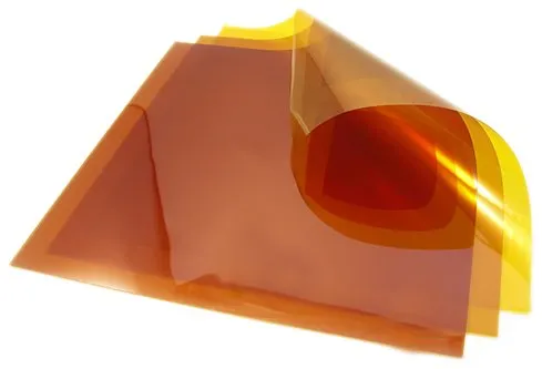
    Polyimide film for flexible printed circuits

    Polyester and Other Cost-Effective Substrate Options

    Polyester (PET) films serve as a cost-effective option for less demanding applications. PET offers good electrical insulation and mechanical flexibility at significantly lower material costs — often 30-50% cheaper than PI. However, its limitations are notable: maximum continuous operating temperature usually ranges from 85°C to 150°C depending on grade, higher moisture absorption, and reduced long-term thermal stability. PET suits static flex-to-install designs in consumer electronics, such as display connections in smartphones or laptops, where extreme temperatures or dynamic motion are absent.

    PET substrates for FPC

    Advanced polymer options fill specific performance gaps:

    ● Polyethylene Naphthalate (PEN): Provides a middle ground with better thermal resistance than PET (up to 180°C) and improved dimensional stability.

    ● Liquid Crystal Polymer (LCP): Delivers ultra-low dielectric constant and dissipation factor, near-zero moisture absorption, and excellent high-frequency performance up to mmWave ranges. LCP excels in 5G antennas, radar modules, and high-speed data applications.

    ● PTFE (Polytetrafluoroethylene) composites: Offer superior chemical resistance and low dielectric loss for RF/microwave circuits, though they present unique processing challenges due to low surface energy.

    Comparative Analysis of Substrate Materials

    This table provides a comparison of common FPC base materials.

    Property

    Polyimide (PI)

    Polyester (PET)

    LCP

    PEN

    Max Operating Temp (°C)

    260+

    85-150

    200+

    150-180

    Moisture Absorption (%)

    1.3-3.0

    0.4-0.8

    <0.02

    0.2-0.4

    CTE (ppm/°C)

    20-30

    20-50

    10-20

    15-25

    Flex Life (Dynamic)

    Excellent (>1M cycles)

    Moderate

    Good

    Good

    Dielectric Constant

    3.4-3.5

    3.0-3.5

    2.9-3.0

    3.0-3.2

    Relative Cost

    High

    Low

    Very High

    Medium

    Typical Applications

    Automotive, Aerospace, Medical

    Consumer Electronics

    RF/5G, High-Speed

    Industrial Sensors

    Engineers must evaluate these properties against specific application requirements rather than selecting based solely on cost.

    Copper Foil Engineering: Rolled Annealed vs Electrodeposited

    While substrate materials form the mechanical and thermal foundation of an FPC, conductor performance is equally critical. In many dynamic flex applications, the copper layer experiences the highest mechanical stress during bending cycles. As a result, selecting the appropriate copper foil structure is often just as important as choosing the right dielectric material. Copper foil selection represents one of the most critical decisions in dynamic FPC design. Two primary types dominate the industry:

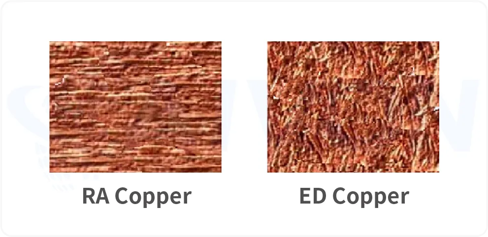
    Rolled Annealed (RA) Copper undergoes a mechanical rolling and annealing process that creates a smooth, elongated grain structure. This microstructure provides superior ductility and resistance to fatigue cracking. When the rolling direction aligns parallel to the primary bend axis, RA copper delivers exceptional flex endurance. Typical thicknesses range from 9μm to 35μm for fine-line applications. RA copper is the preferred choice for applications requiring repeated dynamic flexing, such as hinge connections in foldable devices or automotive camera modules.

    Electrodeposited (ED) Copper grows through electrochemical deposition, resulting in a more columnar grain structure with higher surface roughness on one side. This roughness improves adhesion to dielectrics but reduces ductility compared to RA. ED copper performs adequately in static flex or high-current applications and offers cost advantages, especially in thicker gauges (up to 70μm or more for power distribution).

    Surface treatment and grain orientation significantly affect performance. Reverse treat (RT) or low-profile foils improve etchability and high-frequency characteristics by reducing skin effect losses.

    Rolled annealed and electrodeposited copper foil for FPC fabrication

    Manufacturing and Material Selection Implications

    Copper foil selection directly influences downstream FPC fabrication performance, especially in lamination, etching, and bending reliability.

    ● Dynamic flex reliability: RA copper’s elongated grain structure improves resistance to micro-crack initiation during repeated flexing, making it more suitable for high-cycle bending structures.

    ● Lamination adhesion: ED copper’s naturally rougher surface enhances bonding strength with dielectric materials, improving peel strength in multilayer constructions.

    ● Etching precision: Lower-profile treated foils (reverse treated or very low profile ED/RA) improve line definition and reduce undercutting, which is critical for fine-feature circuits.

    ● Thickness and process trade-offs: Thicker ED copper improves current carrying capacity but increases etch difficulty and minimum line/space limitations, requiring tighter process control.

    However, conductor reliability depends on more than copper selection alone. Flexible circuits also require protective materials that shield traces from mechanical damage, moisture, and environmental contamination while preserving bendability. This role is fulfilled by the coverlay system.

    How Coverlay Selection Affects FPC Protection and Flexibility

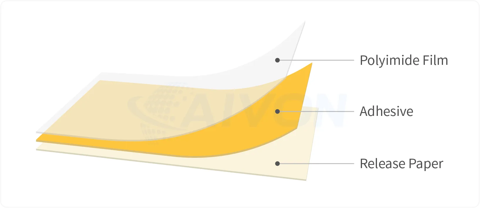
    FPC Coverlay is the primary protective layer for flexible circuits, replacing the solder mask used on rigid PCBs. It consists of a thin polymer film (usually PI or PET) coated with adhesive, providing mechanical support, electrical insulation, and environmental protection against dust, moisture, and chemicals.

    Coverlay structure used in flexible PCB manufacturing

    In production, coverlay thickness (typically 12.5μm, 25μm, or 50μm) creates important trade-offs. Thinner coverlays maximize flexibility and are preferred for tight bend radius applications, but they offer less abrasion resistance. Thicker coverlays improve durability and insulation reliability but can reduce overall circuit flexibility and increase stiffness in dynamic zones.

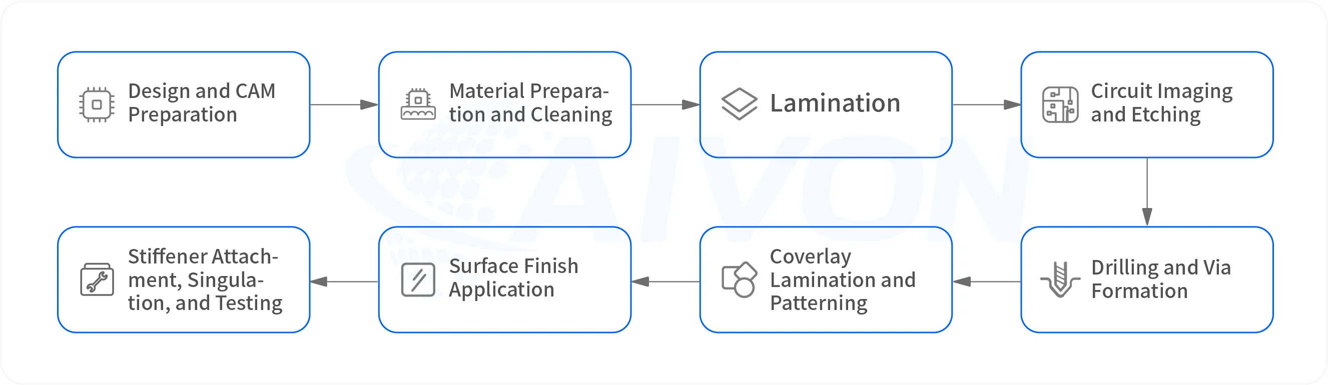
    Flexible PCB manufacturing process from material preparation to testing

    Material choice for coverlay should match the base substrate. PI coverlay paired with PI substrate provides the best thermal matching and long-term reliability in high-temperature or dynamic applications. PET coverlay is often used with PET substrates for cost-sensitive consumer products. The effectiveness of any coverlay system depends heavily on how it is bonded to the underlying circuit structure. Adhesive selection therefore becomes a key engineering consideration, influencing flexibility, thermal resistance, manufacturing yield, and long-term reliability.

    Adhesive Systems in FPC Production: Acrylic vs Epoxy Selection

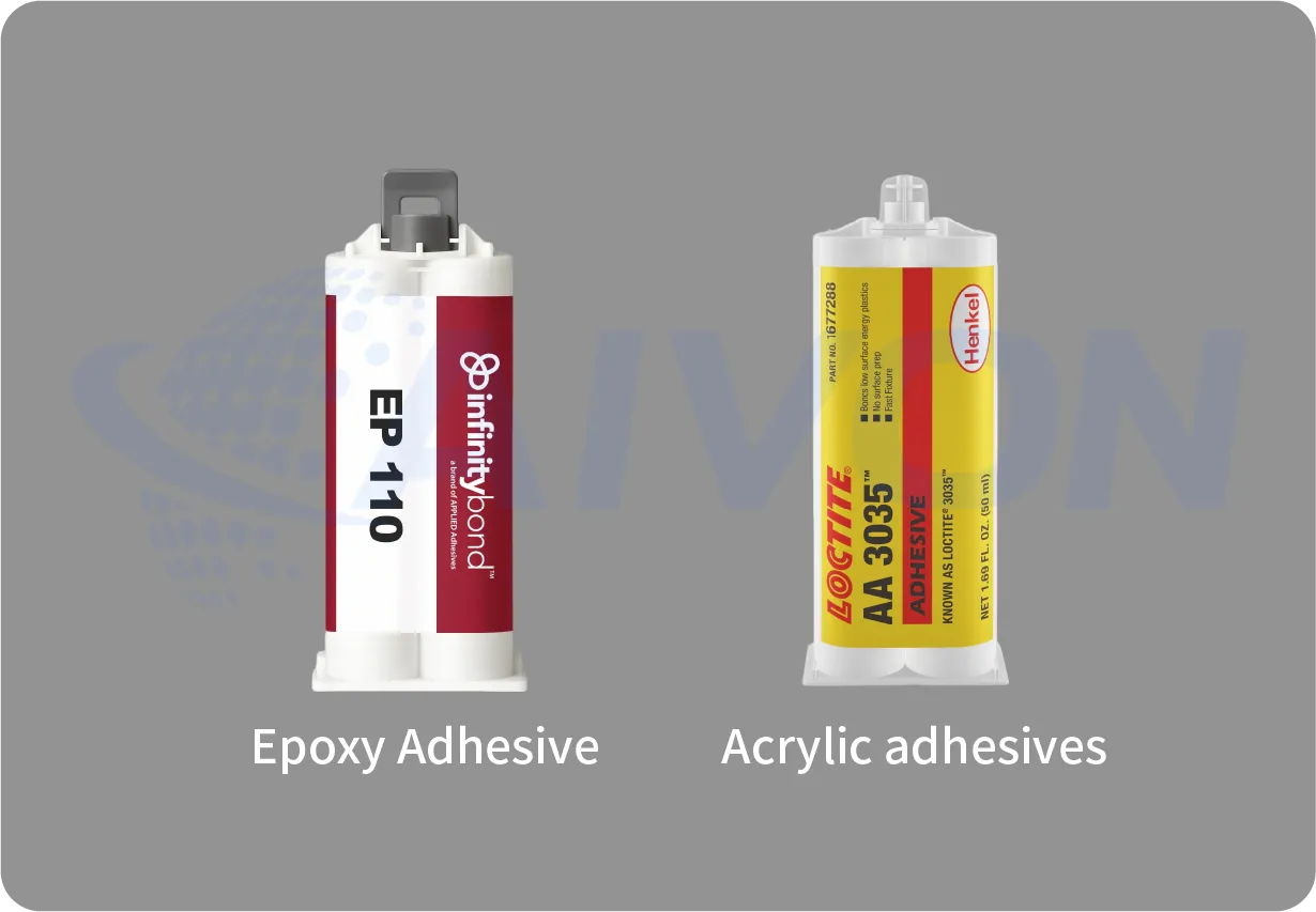
    Acrylic vs Epoxy Adhesive for FPC Production

    Adhesives serve as the bonding bridge between copper foil, substrate, and coverlay. They significantly influence manufacturing process windows, final mechanical properties, and long-term reliability.

    Acrylic adhesives offer excellent flexibility and are widely used in dynamic FPC production. They maintain good peel strength even after repeated bending and thermal aging. Acrylic systems are more forgiving during lamination, providing a wider process window and higher yields in high-flex applications.

    Epoxy adhesives deliver higher bond strength and superior high-temperature performance, making them suitable for automotive and aerospace production where thermal cycling is extreme. However, they are slightly more rigid and require tighter control of lamination temperature and pressure to prevent brittleness or delamination.

    Adhesiveless constructions are increasingly popular in high-performance manufacturing. By using plasma or chemical surface activation to bond copper directly to the dielectric, these structures eliminate adhesive layers entirely. Benefits include thinner overall thickness, better thermal conductivity, improved impedance control, and removal of adhesive-related failure modes. The trade-off is higher technical requirement in lamination equipment and process control.

    Manufacturing Impact Comparison:

    Adhesive Types

    Impact

    Acrylic

    Easier processing, better flexibility, moderate heat resistance.

    Epoxy

    Stronger bonding, higher thermal stability, narrower process window.

    Adhesiveless

    Best electrical and thermal performance, most demanding production controls

    Material and adhesive compatibility must be validated early, as mismatch is a leading cause of delamination during reflow or field use.

    Surface Finish Options for Flexible PCBs

    Once the internal material stack-up has been established, attention shifts to the exposed copper features that will ultimately be assembled and soldered. Surface finish selection plays a critical role in protecting these conductive areas while ensuring reliable electrical and mechanical connections throughout the product lifecycle. Surface finishes protect exposed copper pads and ensure reliable soldering or contact performance while maintaining circuit flexibility.

    Common options in FPC production:

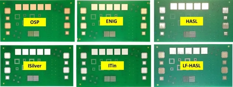
    ● ENIG (Electroless Nickel Immersion Gold): Most popular for high-reliability applications. It offers excellent solderability, corrosion resistance, and wire-bonding capability. The nickel layer provides a hard barrier, while gold ensures long shelf life.

    ENIG Flexible PCB

    ● Immersion Silver (ImmAg): Cost-effective with good conductivity, suitable for high-frequency applications, but more sensitive to tarnishing and handling.

    ● OSP (Organic Solderability Preservative): Lowest cost, ideal for single-reflow consumer products, but limited shelf life and multiple reflow capability.

    OSP FPC

    ● Immersion Tin: Good for press-fit connectors but prone to whisker growth over time.

    Selection depends on assembly process, operating environment, and product lifecycle. For automotive and medical production, ENIG is often mandatory due to its reliability under thermal cycling and humidity exposure.

    In dynamic flex areas, the surface finish must not crack or flake during bending. Thinner finishes generally perform better for flexibility but may compromise long-term protection.

    Although material selection is fundamental, the final performance of an FPC depends equally on how those materials are processed. Even the best substrate, copper foil, and surface finish combinations can fail if manufacturing controls are not properly maintained. Understanding the fabrication process helps explain how material choices translate into real-world product reliability.

    Complete FPC Manufacturing Process and Quality Controls

    FPC fabrication involves specialized processes adapted to thin, flexible materials. Each step introduces variables that can affect final product reliability.

    Flexible PCB manufacturing process from material preparation to testing

    FPC Manufacturing Process Flow:

    1.  Design and CAM Preparation: Engineering review, impedance modeling, and generation of precise tooling data.

    2.  Material Preparation and Cleaning: Plasma or chemical cleaning to ensure optimal adhesion.

    3.  Lamination: Vacuum-assisted bonding of copper to substrate under controlled temperature and pressure profiles. Adhesiveless processes require surface activation.

    4.  Circuit Imaging and Etching: Application of photoresist, UV exposure through high-precision masks, development, and controlled etching. Fine-line capability reaches 25-50μm lines/spaces in advanced facilities.

    5.  Drilling and Via Formation: Laser or mechanical drilling followed by desmear and copper plating for multilayer interconnects.

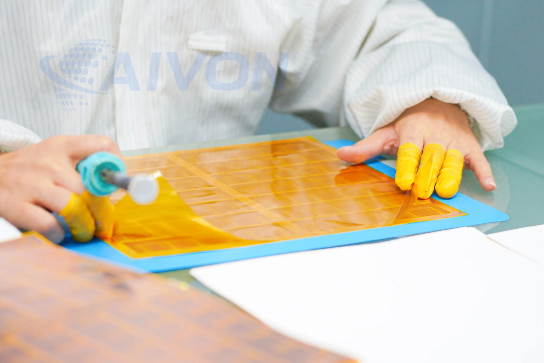
    6.  Coverlay Lamination and Patterning: Precise alignment and windowing for component pads.

    7.  Surface Finish Application: Selective plating or immersion processes.

    8.  Stiffener Attachment, Singulation, and Testing: Precision punching or routing, electrical testing, and AOI inspection.

    Quality Control in FPC Manufacturing:

    Quality consistency in flexible PCB production depends on tightly controlled process parameters across lamination, imaging, etching, and plating stages. Each CTQ directly impacts dimensional stability, electrical performance, and long-term reliability.

    ● Lamination temperature uniformity: Ensures stable resin flow and prevents interlayer stress variation, which directly affects warpage and delamination risk.

    ● Registration accuracy: Critical for multilayer alignment and fine-line circuitry; misregistration can lead to impedance variation and circuit open/short defects.

    ● Etch rate control to prevent undercutting: Maintains consistent conductor geometry and minimizes lateral undercut, which is essential for impedance control and fine pitch definition.

    ● Plating thickness uniformity: Directly influences current carrying capability and long-term fatigue resistance, especially in dynamic flex regions.

    ● Cleanliness levels: Reduces particulate contamination that can cause voids, adhesion failure, or micro-short defects in high-density circuits.

    Compliance with IPC-6013, IATF 16949 (automotive), and ISO 13485 (medical) requires extensive documentation, statistical process control, and regular capability studies.

    Common Flexible PCB Manufacturing Defects and Their Causes

    FPC manufacturing defects can significantly impact product reliability, yield, and overall production efficiency in flexible circuit fabrication. Understanding the most common FPC failure modes, along with their root causes and prevention strategies, is essential for improving process control and manufacturing quality.

    1. Dynamic Fatigue Cracking

    Root causes: Tight bend radii, repeated flexing cycles, excessive copper thinning(FPC Copper Thinning, Trace Width and Etching Control) during fabrication, uneven copper distribution, or material defects introduced during manufacturing.

    Prevention: Use high-ductility RA copper, maintain consistent copper thickness throughout the etching process, optimize plating uniformity, and implement rigorous process controls to minimize stress concentration points.

    Manufacturing Consideration: Even when the flex circuit design is mechanically sound, excessive copper reduction caused by over-etching or poor process control can significantly shorten flex life. Variations in trace geometry, copper thickness retention, and etching uniformity may create localized weak points that accelerate crack initiation under repeated bending.

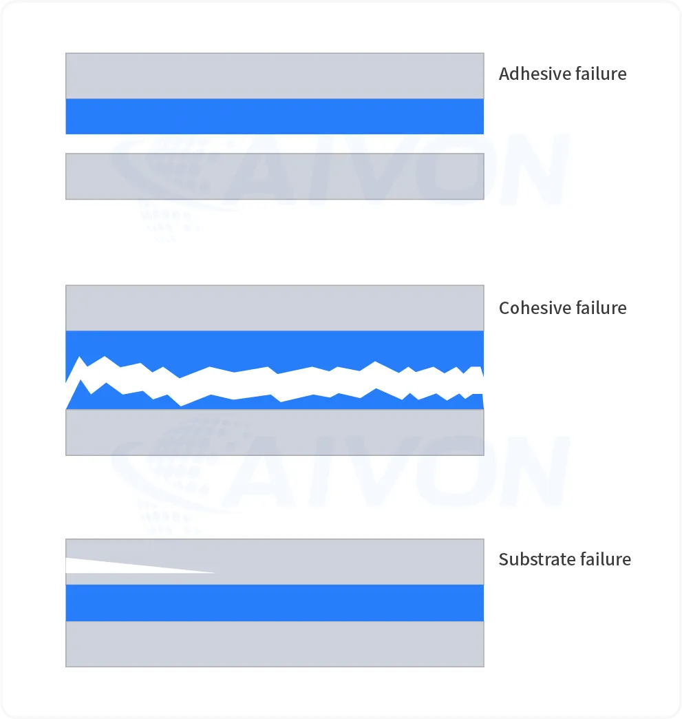
    2.  Delamination

    FPC Delamination

    Root causes: Moisture entrapment, inadequate surface preparation, contamination, thermal mismatch between materials, or insufficient lamination pressure.

    Prevention: Pre-bake incoming materials, optimize vacuum lamination profiles, implement plasma surface treatment, and conduct routine peel strength verification.

    Manufacturing Consideration: Delamination is often linked to inconsistencies in lamination processing rather than material selection alone. Factors such as moisture content, pressure distribution, temperature ramp rates, and adhesive flow behavior directly influence bond integrity and long-term reliability.

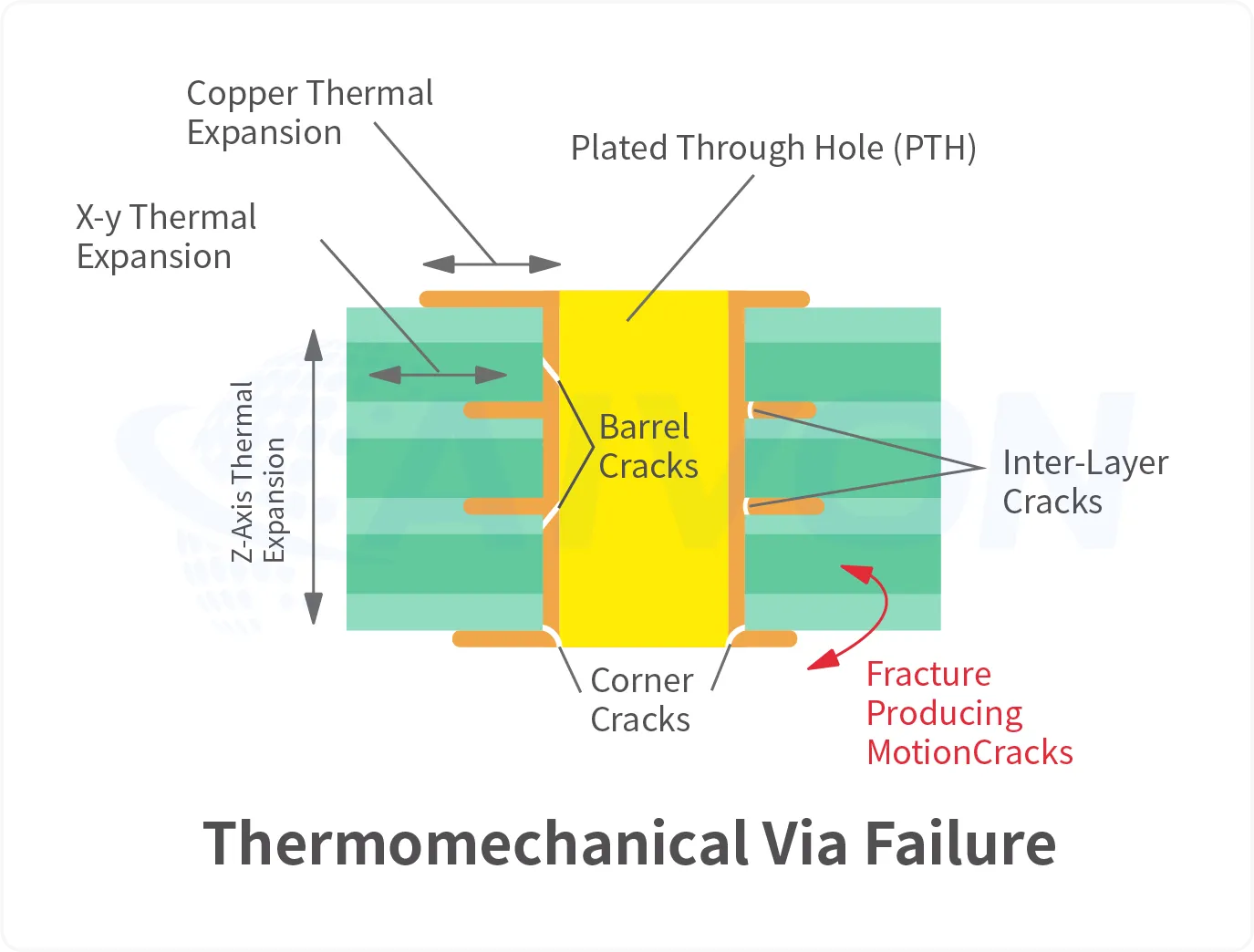
    3.  Copper Cracking at Plated Through Holes (PTH)

    Copper Cracking at Plated Through Holes

    Root causes: Brittle copper deposits, insufficient plating thickness, thermal cycling stress, or defects introduced during drilling and metallization.

    Prevention: Optimize copper plating chemistry, maintain uniform plating thickness, improve hole wall preparation, and verify plating quality through cross-section analysis.

    Manufacturing Consideration: PTH reliability depends heavily on drilling quality, desmear effectiveness, and copper plating consistency. Variations in hole wall preparation or plating ductility can create stress concentration zones that eventually lead to barrel cracking and electrical failure.

    4.  Coverlay Voids and Adhesion Failure

     Coverlay Voids

    Root causes: Surface contamination, trapped air, improper vacuum lamination settings, adhesive flow issues, or material incompatibility.

    Prevention: Implement strict cleaning procedures, optimize lamination pressure and temperature profiles, utilize vacuum-assisted lamination, and perform routine cross-section inspections.

    Manufacturing Consideration: Coverlay quality is highly sensitive to lamination conditions. Poor vacuum performance, inadequate adhesive flow, or inaccurate alignment can result in void formation, lifting, and reduced environmental protection of the circuitry.

    CEZON Case Study: Coverlay Delamination on Thick Copper FPC

    Customer Requirement:

    A customer required a 2-layer flexible PCB with a finished copper thickness of 80 μm. The initial design used our standard coverlay construction, model ASC-FC125SKT1, which consists of 25 μm polyimide film with a 25 μm adhesive layer.

    Challenge:

    After lamination and subsequent processing, localized delamination occurred between the coverlay and the copper surface. In some areas, the coverlay even cracked during handling and assembly. This significantly weakened the mechanical integrity of the flex circuit and posed a reliability risk.

    Root Cause Analysis:

    The root cause was insufficient adhesive thickness relative to the copper profile. With an 80 μm finished copper thickness, the 25 μm adhesive layer lacked adequate volume and flow capability to properly encapsulate the copper traces and fill the spaces between them. This resulted in reduced bonding area and weak interfacial adhesion. Once delamination initiated, the coverlay lost mechanical support and became prone to cracking under even moderate handling stress.

    In practice, we have observed that when finished copper thickness exceeds approximately 50–60 μm, standard 25 μm adhesive coverlay often becomes marginal, especially in designs with dense traces or larger copper features.

    Solution:

    The coverlay construction was changed from 25 μm PI + 25 μm adhesive to 25 μm PI + 50 μm adhesive. The thicker adhesive provided significantly better resin flow and encapsulation around the thick copper, greatly increasing the effective bonding area and interfacial strength between the coverlay and copper surface.

    Result:

    After implementing the revised coverlay, the delamination issue was completely resolved. The flex circuits passed subsequent mechanical handling, bending, and reliability verification with no further coverlay-related defects. The change also improved overall structural robustness without compromising flexibility in non-critical areas.

    Engineering Note:

    This case highlights an important DFM consideration: adhesive thickness in coverlay selection should be evaluated based on finished copper thickness, not just nominal design requirements. For designs with finished copper ≥ 70 μm, we generally recommend evaluating 50 μm adhesive coverlay early in the design stage to avoid adhesion and mechanical strength issues during production and assembly.

    Flexible PCB Manufacturing for Different Industries

    Flexible PCB for Automotive Electronics

    Automotive electronics use flexible circuits in displays, lighting, sensors, battery systems, cameras, and control modules.

    Designs in the flexible PCB for automotive should consider temperature changes, vibration, mechanical movement, electrical requirements, and long-term reliability. Material selection and bend-area design are especially important for circuits installed in moving or confined spaces.

    Flexible Circuits for Medical Devices

    Medical devices often require compact, lightweight, and reliable interconnections.

    FPCs may be used in diagnostic equipment, monitoring devices, imaging systems, and wearable medical products. The design should consider cleanliness, insulation, flexibility, biocompatibility requirements where applicable, and the conditions of use.

    Flexible PCBs for Wearable Devices

    Wearable products require lightweight and flexible structures. The wearable flexible PCB can help connect sensors, displays, batteries, and other compact electronic components.

    The circuit should be designed around the product’s movement and shape. Bend radius, material thickness, component placement, and protective layers all affect comfort and reliability.

    Flexible Circuits for Aerospace and Defense Systems

    Aerospace flexible PCB solutions are used in applications where compact routing, weight control, vibration resistance, and stable electrical performance are important. Flexible circuits can help connect components in confined spaces while supporting lightweight and complex system designs.

    Material selection and manufacturing controls should be matched to the operating environment. Depending on the application, the aerospace flexible PCB may also require application-specific inspection, environmental testing, and reliability validation.

    Flexible PCBs for Consumer Electronics

    Consumer electronics commonly use FPCs in phones, tablets, cameras, displays, keyboards, and other compact devices.

    These applications often require a balance between thinness, flexibility, fine features, assembly compatibility, and cost.

    Flexible Circuits for Industrial and Telecommunications Equipment

    Industrial and telecommunications equipment may use flexible circuits for displays, sensors, control panels, connectors, and compact internal wiring.

    The material and circuit structure should be selected according to the electrical load, mechanical conditions, temperature, and expected service life.

    Rigid-Flex vs Pure Flex Decision Framework:

    ● Pure Flex: Maximum conformability and lowest weight.

    ● Rigid-Flex: Better component stability and assembly yields.

    ● Total cost analysis often favors rigid-flex in complex systems despite higher upfront tooling.

    Engineers should conduct thorough design reviews, prototype validation, and supply chain qualification early in the development cycle.

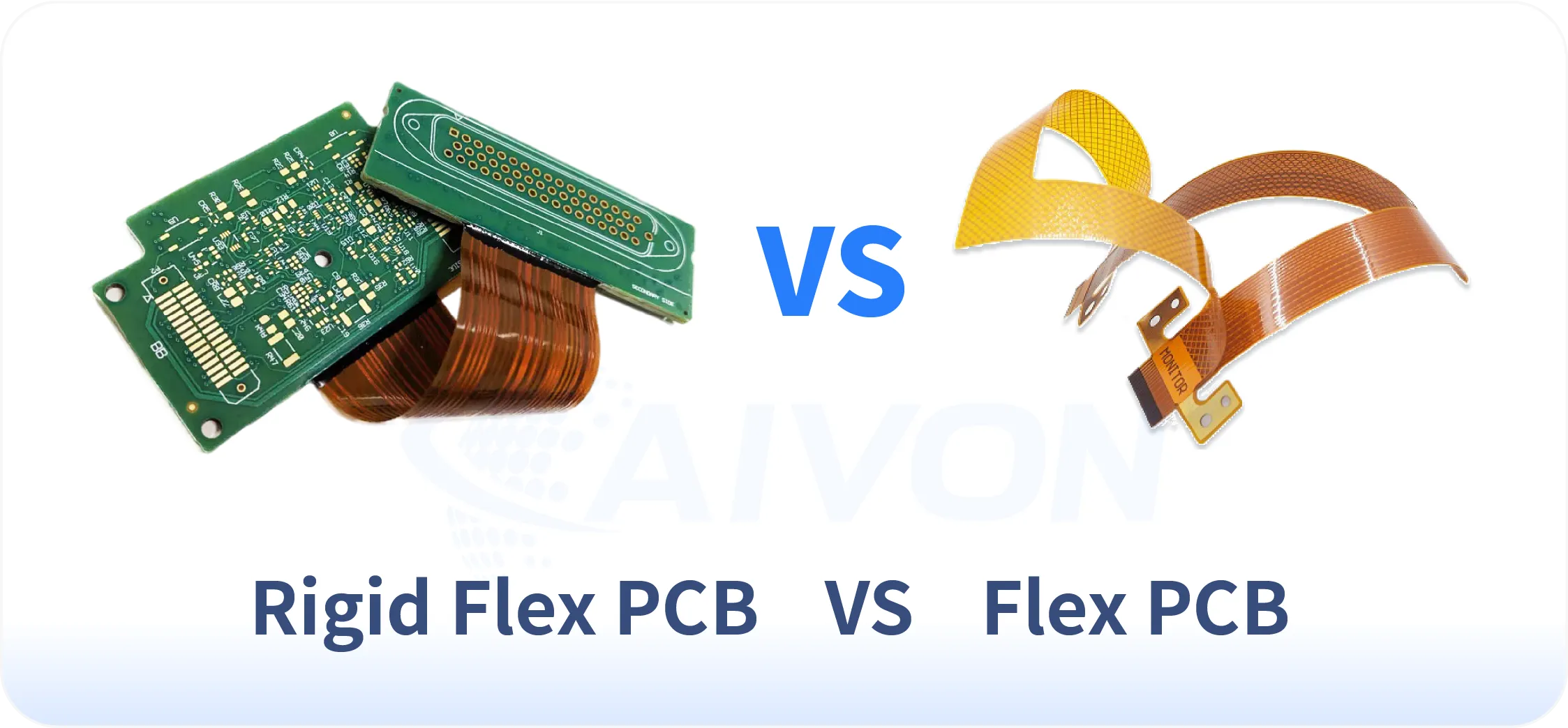
    FPC vs Rigid-Flex: Manufacturing and Material Selection Trade-offs

    Comparison of pure FPC and rigid-flex PCB structures

    From a production and material selection perspective, choosing between pure Flexible PCB (FPC) and Rigid-Flex constructions involves balancing manufacturing complexity, material cost, process yield, and production scalability.

    Pure FPC uses flexible substrates (primarily PI or PET) throughout the entire circuit. Manufacturing is specialized but relatively streamlined, focusing on flexible material handling, precise coverlay alignment, and singulation. Production advantages include lower material diversity, simpler lamination cycles in many cases, and better suitability for high-volume dynamic flex applications. However, attaching components can be more challenging, often requiring additional stiffeners, which adds secondary bonding processes.

    Rigid-Flex combines rigid PCB areas (typically FR-4 or high-Tg materials) with flexible PI sections in a single laminated structure. This hybrid approach significantly increases manufacturing complexity. It requires multiple lamination cycles, precise zonal registration between rigid and flex materials, and careful management of CTE mismatch at transition zones. Production yields are generally lower than pure FPC, especially in multilayer builds, due to higher risk of delamination, warpage, and via stress at the rigid-flex interface.

    Key Manufacturing and Material Comparison:

     Property

    Pure FPC

    Rigid-Flex

    Material Cost

    Pure FPC is usually lower cost as it uses uniform flexible materials.

    Rigid-Flex requires both rigid laminates and flexible PI films, plus specialized no-flow prepregs, increasing material cost by 40-80%.

    Process Complexity

    Pure FPC involves fewer lamination steps.

    Rigid-Flex requires sequential lamination (often 3-5 stages), plasma desmear optimization for different material types, and more stringent registration control (±25μm or tighter).

    Production Yield

    Pure FPC typically achieves higher yields (85-95% in mature processes)

    Rigid-Flex yields are lower (70-85%) due to interface challenges, especially in high-layer counts.

    Lead Time

    Pure FPC prototypes and production are faster.

    Rigid-Flex often adds 1-2 weeks due to complex tooling and multi-stage lamination.

    Scalability

    Pure FPC is easier to scale for high-volume consumer applications.

    Rigid-Flex is better suited for medium-volume, high-reliability programs (automotive, medical, aerospace).

    Conclusion

    Successful flexible PCB manufacturing depends on the right combination of materials, circuit structure, fabrication processes, and quality controls.

    Polyimide, copper foil, coverlay, adhesives, stiffeners, and surface finishes all influence the performance of the finished FPC. At the same time, trace routing, bend radius, layer registration, lamination, plating, and inspection must be carefully managed during flex PCB fabrication.

    Whether the project requires a simple single-sided circuit, a multilayer FPC, a dynamic-flex design, or a rigid-flex structure, early design review and close communication with the manufacturer can help reduce production risks.

    By selecting materials based on actual application requirements and validating the manufacturing process before volume production, engineers can achieve more reliable, manufacturable, and cost-effective flexible circuit solutions.

    FAQs

    Q1: When is RA copper preferred over ED copper?

    A1: RA copper is preferred for applications requiring frequent bending or long flex life because of its excellent fatigue resistance. ED copper is generally suitable for static flex designs where cost efficiency is a higher priority.

    Q2: How many bend cycles can a quality PI FPC achieve?

    A2: A well-designed PI-based FPC can typically withstand more than 500,000 bend cycles, with some dynamic flex applications achieving several million cycles. Actual performance depends on factors such as bend radius, copper type, and circuit design.

    Q3: What standards apply to automotive and medical FPC production?

    A3: Automotive FPCs are commonly manufactured under IATF 16949 quality systems and IPC-6013 requirements. Medical FPCs typically follow ISO 13485 standards and require enhanced traceability and process control.

    Q4: How does coverlay thickness impact performance?

    A4: Thicker coverlays provide better mechanical protection and insulation but reduce overall flexibility. Most FPC designs use coverlays between 25 μm and 50 μm to balance durability and bending performance.

    Q5: What are typical lead times for custom FPC projects?

    A5: Prototype FPC projects typically require 8 to 20 days, while production volumes often take 2 to 5 weeks depending on design complexity and material availability. Early design validation can help shorten development timelines.

    Q6: How do material choices affect total project cost?

    A6: Material selection influences not only manufacturing cost but also reliability, yield, and product lifespan. Higher-performance materials often reduce long-term failure risks and can lower the overall cost of ownership.

    Q7: Are there cost-effective alternatives to FPCs for large EV battery packs?

    A7: For large EV battery packs, busbars, wire harnesses, flexible flat cables (FFCs), and modular wiring assemblies may be cost-effective alternatives to FPCs. Busbars are suitable for high-current connections, while wire harnesses and FFCs can support battery monitoring and signal routing. The best option depends on the pack structure, electrical requirements, available space, and assembly process.

    Q8: What factors should be considered when selecting FPC materials?

    A8: FPC material selection should consider flexibility, bend requirements, operating temperature, electrical performance, mechanical strength, and environmental exposure. The material should match the circuit structure and the conditions expected during assembly and use.

    Q9: How can designers reduce the cost of flexible PCB manufacturing?

    A9: Designers can help control flexible PCB manufacturing costs by simplifying the circuit structure, avoiding unnecessary tight tolerances, selecting practical material options, and improving panel utilization. Early DFM review can also reduce redesigns and production issues.

    Q10: What is the difference between FPC fabrication and FPC assembly?

    A10: FPC fabrication produces the flexible circuit itself, including its conductive pattern, insulation, openings, and surface finish. FPC assembly adds components, connectors, or other parts to the fabricated circuit. Some applications require only bare FPCs, while others need a complete flexible circuit assembly.

    Q11: How can flexible circuits be protected during installation and operation?

    A11: Flexible circuits can be protected through suitable reinforcement, connector support, controlled routing, and secure fixing. Designers should avoid sharp bends, excessive mechanical stress, and unsupported areas that may be damaged during installation or repeated movement.

    Q12: What should be considered when choosing an FPC manufacturer?

    A12: When choosing an FPC manufacturer, consider its material capabilities, fabrication experience, DFM support, inspection methods, prototype services, production capacity, and quality documentation. The supplier should also be able to meet the reliability and traceability requirements of the intended application.

    Get in Touch


      HDI PCB Manufacturing Guide: Microvia Technology, Structures and Capabilities

      HDI PCB manufacturing is defined by one fundamental difference from conventional multilayer production: the controlled formation, filling, and stacking of laser-drilled microvias. This guide addresses the complete HDI production process from the microvia perspective, covering every critical stage that determines density, yield, reliability, and cost.

      Readers will find a systematic examination of HDI board structures, laser drilling principles and process windows, copper and epoxy microvia filling materials and methods, sequential build-up flow for any-layer interconnect, in-process inspection and reliability testing, real manufacturing case studies, and the dominant cost drivers.

      The content is written for process engineers, design engineers, procurement specialists, and technical decision-makers who need to understand not only what HDI is, but how microvia technology shapes every manufacturing decision, and final reliability qualification. By focusing on the microvia as the central process element, the guide provides the practical engineering logic required to specify, manufacture, and qualify HDI boards for high-density applications.

      What Is HDI PCB Manufacturing?

      An HDI PCB is a printed circuit board that achieves significantly higher wiring density than a conventional multilayer board. It does this by using laser-drilled microvias, sequential build-up layers, and finer traces and spaces. Instead of relying mainly on mechanically drilled through-holes that pass through the entire board, an HDI board connects only the layers that need to be linked. This approach allows more routing channels in a smaller area and supports finer-pitch components such as high-density BGAs.

      Conventional boards rely on large mechanically drilled through-holes that consume routing space and create long stubs. HDI manufacturing replaces most of these with small microvias that connect only the needed layers. This reduces pad size, shortens signal paths, and allows more traces to fit between fine-pitch components.

      HDI PCB production

      Microvias are the core of HDI production. The ability to form, clean, fill, and stack these tiny laser-drilled holes determines whether higher-density structures can be built reliably. Poor microvia quality leads directly to registration problems, voids, and early failures, which is why every major process step in HDI manufacturing centers on microvia control.

      HDI PCB Types and Structures

      HDI boards are classified by sequential build-up architecture. Structure determines process sequence, via architecture options, material selection, yield, and ultimately cost and reliability. Misclassification of structure remains a primary source of cost overruns and reliability failures.

      Construction

      Typical Via Type

      Relative Density

      Relative Cost

      Typical Applications

      1+N+1

      Blind microvias + core through-holes

      Moderate

      Lowest

      Consumer, mid-density modules

      2+N+2

      Stacked or staggered microvias

      High

      Medium

      Smartphones, automotive ADAS

      Any-layer

      Fully stacked microvias on every layer

      Highest

      Highest

      AI modules, high-layer-count compute, ultra-thin wearables

      1+N+1 structure

      The 1+N+1 structure places a single build-up layer on both sides of a conventional multilayer core. Microvias connect only the outer layers to the adjacent core layers. This configuration supports moderate-density designs with 0.5–0.65 mm pitch BGAs at relatively low cost and is the most common entry-level HDI construction.

      2+N+2 structure

      The 2+N+2 and higher sequential build-up structures add two or more dielectric and copper layers on each side of the core. Each additional pair requires another lamination, laser-drill, and plating cycle. These structures enable stacked or staggered microvias and support finer-pitch packages down to 0.4 mm.

      Any-layer structure

      Any-layer or ELIC structures remove the distinction between core and build-up. Every dielectric layer is laser-drilled and filled so that a microvia can connect any pair of adjacent layers. This architecture delivers the highest wiring density and the thinnest constructions, yet it multiplies laser and plating cycles and places the strictest demands on registration accuracy and dielectric thickness uniformity.

      Three Microvias in HDI PCBs

      Within these structures three via architectures are available. Staggered microvias offset successive vias laterally, reducing registration risk and eliminating the need for complete copper fill. Stacked microvias align vertically to form a continuous copper column, maximizing density and enabling true via-in-pad designs, but they demand void-free fill and precise registration at every interface. Skip vias and combinations of microvias with mechanical through-holes provide additional routing flexibility when selective layer connections are required.

      Typical cross-sections show the progression clearly: a 1+N+1 board contains single-depth microvias landing on the outer core layers; a 2+N+2 section reveals either staggered or stacked pairs; an any-layer micrograph displays continuous stacked columns running through the full thickness. Capture-pad size, residual copper at the via bottom, and plating uniformity remain the measurable indicators of process capability for each type.

      HDI PCB Material for Sequential Build-Up

      HDI boards rely on a combination of core and build-up materials that must work together through multiple lamination and laser-drilling cycles. The core is usually a high-Tg FR-4 or similar rigid laminate chosen for dimensional stability. It provides the mechanical backbone that keeps the board flat while thinner layers are added on both sides.

      On top of the core, manufacturers apply specialized build-up dielectrics. Resin-coated copper (RCC) is widely used because its resin formulation supports clean laser ablation and strong adhesion to copper. Laser-drillable prepregs serve the same purpose. These thin dielectrics allow microvias to be formed accurately while keeping the overall board thickness low. Their thickness is tightly controlled, since even small variations affect impedance and the aspect ratio of the vias.

      Copper also plays a dual role. Thin electrodeposited copper foils are preferred for fine-line etching on the outer and build-up layers. After laser drilling and desmear, an electroless copper seed layer is deposited, followed by electrolytic plating that builds the circuit traces and fills the microvias. The plating system must deliver good throwing power so that small vias can be filled uniformly without voids.

      Material selection influences nearly every subsequent process step. Dielectrics that laser-drill cleanly leave less residue and improve plating adhesion. Stable core materials reduce warpage during sequential lamination. Copper foils and plating chemistries that support fine features and void-free filling determine whether stacked microvias can be produced reliably. Choosing materials that match the laser, desmear, and plating processes is therefore essential for consistent yield and long-term reliability in HDI manufacturing.

      Microvia Technology in HDI PCB Manufacturing

      Microvia Formation and Laser Drilling

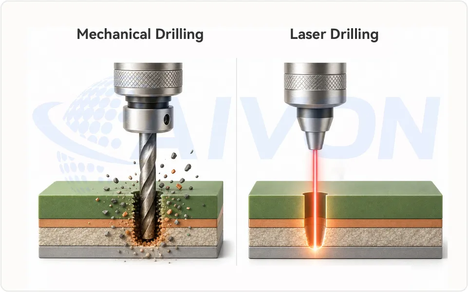
      Microvias are the single biggest reason HDI boards can achieve much higher density than conventional multilayer boards. Instead of drilling all the way through the board with a mechanical drill, manufacturers use a laser to create very small holes that only connect the specific layers needed. The quality of these laser-drilled holes largely decides how well the vias can be plated later, how reliable stacked structures will be, and how many defects appear in production.

      Laser Drilling in High Density PCB Manufacturing

      The laser removes the dielectric material in one of two ways. Some lasers mainly heat the material until it vaporizes, which is called photothermal ablation. Others break the chemical bonds in the resin more directly while also generating some heat, which is called photochemical ablation.

      CO₂ lasers work primarily by heating. They are fast and economical, which makes them the common choice for vias larger than about 75 µm. UV lasers combine bond-breaking with heating. They create cleaner sidewalls and can produce much smaller vias, often down to 25 to 50 µm.

      Which laser works best depends on the dielectric material itself. Different resins absorb laser energy differently. The material’s glass-transition temperature and the amount of filler it contains also influence how cleanly the laser can cut and how much residue is left behind.

      Once the laser type is chosen, four practical settings control the final hole shape: the energy of each pulse, how many pulses are fired per second, the size of the laser spot, and the exact focus position. These settings determine the entrance diameter at the top of the via, how much the sidewalls taper, and how much copper remains at the bottom. Too much energy can make the hole too wide or damage the landing pad. Too little energy leaves resin residue that later causes plating problems.

      After the laser finishes drilling, a cleaning step called desmear is essential. Chemical or plasma treatment removes any remaining resin smear and prepares the surface so copper can adhere properly. Incomplete desmear is still one of the most common reasons for poor adhesion and voids in the finished microvia.

      Methods of Microvia Filling

      The microvia filling process employs distinct methods tailored to material type and production scale. Copper filled microvias rely on electrolytic plating, starting with electroless copper seed layer deposition after laser drilling and desmear. Pulse reverse electroplating then fills the via from bottom to top, minimizing voids through controlled current density and reversal. This super-filling technique creates a slight dome or flat top, which lamination flattens. Epoxy filled microvias use screen printing or vacuum-assisted dispensing to inject paste into vias, followed by thermal curing.

      For copper filling, the process sequence includes panel electroplating for initial barrel plating before targeted via filling. Reverse pulse plating parameters adjust additive concentrations to promote uniform growth. Epoxy methods accommodate higher aspect ratios since paste flows under pressure, but require stencil design for precision. Hybrid approaches combine conductive paste with plating for through-hole filling in complex boards. Factories optimize these methods per IPC guidelines to achieve consistent results across panels.

      Conductive pastes for epoxy filled microvias incorporate metal flakes suspended in resin, screened through fine meshes matching via pitch. Curing schedules align with board bake-out to prevent outgassing. Copper methods demand cleanroom controls to avoid contamination during plating baths. Both approaches cap filled vias with photoresist or dielectric for protection.

      HDI PCB Manufacturing Process and Key Challenges

      HDI boards are built using a sequential process rather than the single lamination cycle used for conventional multilayer boards. The manufacturer starts with a core, then adds dielectric and copper layers one step at a time, drilling and plating microvias after each addition. This sequence is repeated until the required number of build-up layers is reached.

      A typical cycle includes the following steps: dielectric material, such asprepreg or resin-coated copper, is laminated onto the existing structure, the laser drills the microvias to the target pads, desmear cleans the holes, electroless and electrolytic copper are applied to form the interconnect, and the circuit pattern is imaged and etched. After inspection, the next dielectric layer is added and the cycle begins again.

      For simple 1+N+1 designs the sequence happens only once on each side. For 2+N+2 or higher constructions the same sequence is repeated multiple times.

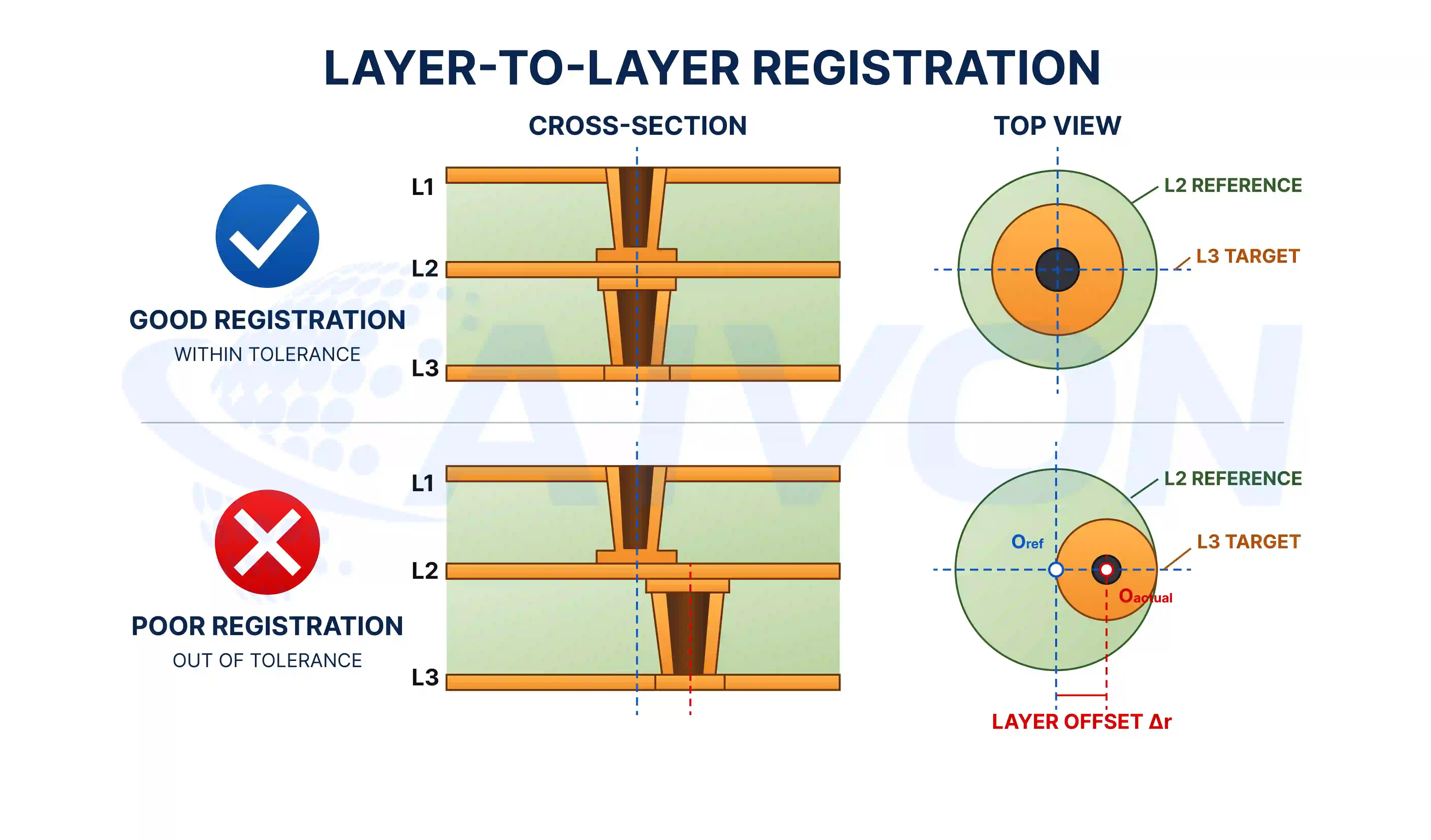
      Three practical challenges dominate the HDI manufacturing process and largely determine yield and final quality.

      layer-to-layer registration in hdi manufacturing process

      The first is layer-to-layer registration. Each new set of microvias must land accurately on the pads of the previous layer. Even small misalignment accumulates as more layers are added, so optical or X-ray alignment systems and careful compensation are required to keep the error within acceptable limits.


      The second challenge is dielectric thickness and surface flatness. The thickness of each new dielectric layer must stay consistent across the panel. Variation affects impedance control and also changes the laser focus for the next drilling step. Uneven surfaces after plating or planarization make it harder to achieve reliable registration on the following layer.

      The third challenge is residual stress and warpage. Every lamination and plating step introduces stress into the board. As more sequential layers are added, the stress builds up and can cause the panel to warp. Symmetric copper distribution, controlled cooling after lamination, and occasional intermediate stress-relief steps are used to keep warpage within the limits needed for fine-pitch assembly.

      These three issues become more demanding as the number of sequential cycles increases. Process capability in registration accuracy, thickness control, and warpage management therefore sets the practical limit on how complex an HDI structure can be manufactured reliably.

      HDI PCB Manufacturing Quality Control and Reliability Testing

      HDI boards contain many internal features that cannot be checked by simple visual inspection. Because microvias, stacked connections, and thin dielectric layers are hidden inside the board, manufacturers must use a combination of in-process checks, non-destructive testing, and formal reliability testing to ensure consistent quality.

      During production, automated optical inspection (AOI) is used on outer layers to catch pattern defects, opens, and shorts. For internal features such as buried or stacked microvias, X-ray inspection is essential. X-ray can reveal voids, incomplete fills, and misregistration that would otherwise go unnoticed until the board fails later.

      CEZON also take microsection samples at key process steps. These cross-sections allow engineers to measure plating thickness, check for residual resin, and confirm that the via walls and interfaces are properly formed.

      After the boards are completed, reliability testing is performed to verify that the structure can survive the stresses of assembly and field use. Common tests include thermal cycling, interconnect stress testing (IST), and conductive anodic filament (CAF) testing.

      Test

      Purpose

      Thermal Cycling

      Checks for cracks or opens caused by repeated temperature changes.

      IST

      Monitors resistance during rapid heating and cooling to detect developing failures.

      CAF Testing

      Evaluates the risk of conductive path formation under humidity and electrical bias.

      Several HDI microvia defects and failure modes appear more often in HDI than in conventional boards. Corner cracks can form at the bottom of a microvia if the laser hole is poorly shaped or residual stress is high. Interface separation can occur between stacked vias when the copper fill is incomplete. CAF growth may develop along moisture paths or contaminated interfaces. Warpage caused by uneven stress during sequential lamination can also affect assembly yield.

      Manufacturers reduce these risks through process control rather than relying only on final testing. They keep microvia aspect ratios moderate, ensure thorough desmear after laser drilling, maintain tight control of plating chemistry, bake boards to remove moisture, and use symmetric copper distribution to limit warpage. Each production lot is typically qualified against the specific thermal and humidity conditions of the end application, following the relevant IPC performance class requirements. This combination of in-process inspection, targeted reliability testing, and disciplined process control is what allows HDI boards to meet the demands of high-density applications.

      CEZON’s HDI PCB Fabrication and Manufacturing Capabilities

      CEZON maintains tight process control over the critical parameters that directly affect HDI interconnect reliability, dimensional accuracy, and production yield.

      Key HDI Control

      CEZON Process Control

      Why It Matters

      Microvia Filling

      Blind-via dimple controlled to ≤25 μm

      Ensures reliable microvia structures and supports high-density interconnections

      Hole Accuracy

      PTH: ±0.076 mm; NPTH: ±0.05 mm

      Maintains accurate interlayer connections and component alignment

      Fine-Line Control

      Trace width/spacing tolerance controlled to ±20%

      Supports the tight geometries required for high-density HDI layouts

      Board Flatness

      Board warpage controlled to ≤0.75%

      Helps maintain dimensional stability during assembly

      Plating & Copper Distribution

      Auxiliary copper patterns can be added to balance plating

      Reduces plating imbalance and helps control board warpage

      Quality & Traceability

      Electrical testing and production traceability marking

      Provides additional verification and process traceability

      These controls demonstrate that CEZON’s HDI manufacturing is not limited to standard PCB production. We actively evaluate microvia geometry, via filling, drilling tolerances, copper distribution, and board deformation during engineering review and production to ensure that the design can be manufactured reliably.

      Rather than simply following the supplied Gerber files, CEZON’s engineering team reviews critical HDI structures and identifies potential manufacturing risks before production. When a design uses non-standard laser-drilled blind vias or buried vias that may affect filling and reliability, we evaluate the structure and recommend manufacturable dimensions accordingly.

      Real HDI PCB Manufacturing Case: Optimizing Blind and Buried Via Dimensions

      For one HDI project, the customer’s Gerber files specified 0.2 mm blind vias between IN1–1/2 and IN4-Back–6/5. Because CEZON manufactures HDI blind vias using laser drilling, this diameter was outside the preferred range for the laser-drilled structure.

      During engineering review, CEZON identified the issue and recommended reducing the blind-via diameter from 0.2 mm to 0.1 mm to better suit the laser drilling process.

      reducing the blind-via diameter from 0.2 mm to 0.1 mm

      The same design contained 0.6 mm buried vias. Since a large buried via diameter can make via filling more difficult, CEZON recommended reducing the diameter to 0.3 mm to improve manufacturability and filling performance.

      Design Feature

      Customer Gerber

      CEZON Recommendation

      Engineering Consideration

      Blind Via

      0.2 mm

      0.1 mm

      Optimized for laser drilling

      Buried Via

      0.6 mm

      0.3 mm

      Improves via-filling manufacturability

      This case demonstrates CEZON’s DFM-driven HDI engineering capability: we don’t simply manufacture according to the submitted files. Our engineers evaluate whether critical HDI structures are compatible with the actual manufacturing process and proactively recommend design adjustments to improve manufacturability, yield, and interconnect reliability.

      Conclusion

      HDI manufacturing is built around the microvia. The choice of board structure, the precision of laser drilling, the quality of via filling, and the control of sequential build-up all depend on how well these small interconnects are formed and maintained. When registration, dielectric thickness, and warpage are kept under control, denser and more complex designs become manufacturable at practical yields.

      In-process inspection, targeted reliability testing, and clearly defined process limits turn these technical requirements into consistent results. Boards that pass these controls deliver the higher interconnect density, shorter signal paths, and long-term reliability that modern electronics demand.

      Understanding the complete chain, from microvia formation through final process discipline, allows engineers and procurement teams to specify and produce HDI boards that perform as intended.

      FAQs

      Q1: What Is HDI PCB Technology?

      A1: HDI PCB technology is an advanced PCB manufacturing approach that uses fine-line traces, microvias, sequential build-up structures, and high-density routing to fit more interconnections into smaller boards. It enables compact designs, shorter signal paths, improved electrical performance, and higher component density. HDI technology is widely used in smartphones, automotive electronics, medical devices, telecommunications, and other high-performance electronic products.

      Q2: What Latest Techniques Enable High-Precision Impedance Control in HDI PCBs?

      A2: Latest HDI techniques for high-precision impedance control include advanced stackup design, tightly controlled dielectric thickness, fine-line routing, low-loss materials, optimized copper thickness, and continuous reference planes. 3D electromagnetic simulation and automated impedance analysis can further verify high-speed structures before fabrication. These methods help control trace impedance, minimize signal reflections and crosstalk, and improve signal integrity in high-density PCB designs.

      Q3: What is the practical difference between staggered and stacked microvias in terms of reliability?

      A3: Staggered microvias eliminate the copper-to-copper interface between successive microvias, removing a common crack-initiation site. Stacked microvias concentrate stress at each filled junction, making void-free plating and tight process control essential. For applications requiring more than two stacked levels, staggered or hybrid architectures generally provide higher field reliability with lower process risk.

      Q4: When does any-layer HDI become more cost-effective than sequential 2+N+2?

      A4: Any-layer HDI generally costs more than 2+N+2 until the required interconnect density makes the higher process cost worthwhile. The crossover can occur when package pitches fall below approximately 0.3 mm or when total board thickness must remain below about 0.6 mm and conventional sequential build-up cannot provide sufficient routing density.

      Q5: What laser parameters most strongly affect via fill quality?

      A5: Entrance diameter, taper angle, and residual copper thickness at the via bottom strongly affect subsequent plating quality. Laser energy density and pulse count must be optimized to produce clean via bottoms and residue-free sidewalls. Because different dielectric materials respond differently to laser energy, material-specific process windows are essential.

      Q6: What are the dominant cost drivers in HDI production?

      A6: The major HDI cost drivers include sequential lamination cycles, copper-fill and planarization processes, laser drilling time, and yield losses caused by registration or via-fill defects. Higher-performance materials can add cost, but the number of additional process steps usually has a greater impact on the overall HDI premium.

      Q7: What IPC/industry standards govern HDI microvia acceptance?

      A7: IPC-6012 and IPC-6016 define relevant performance requirements and microvia criteria, while IPC-2226 provides HDI design guidance and classification. Automotive and aerospace applications may also require additional thermal cycling, interconnect stress testing (IST), and customer-specific reliability requirements beyond the baseline IPC standards.

      Q8: How do different dielectrics change laser drilling and plating windows?

      A8: Different dielectric materials require different laser and desmear process windows. High-filler FR-4 may require higher laser energy and more aggressive desmear, while polyimide and PTFE-based materials can ablate more readily but may leave residues that require thorough removal. Low-loss materials may also benefit from UV laser processing for cleaner sidewalls and require tighter control of plating chemistry to maintain adhesion.

      Q9: What are the main differences between copper-filled microvias and epoxy-filled microvias?

      A9: Copper-filled microvias use electroplating to create a conductive metallic fill, providing excellent electrical conductivity and heat transfer and making them well suited for stacked vias and high-current applications. Epoxy-filled microvias use a resin-based fill and are generally lower cost, making them suitable for applications where insulation or simpler processing is sufficient. Copper fills typically offer better thermal-cycle reliability, while epoxy fills can be more susceptible to stress and delamination due to differences in thermal expansion.

      Q10: Which companies can produce HDI boards with laser drilling capabilities?

      Companies with HDI manufacturing capabilities typically use CO₂ or UV laser drilling systems to produce microvias for high-density multilayer boards. At Cezon, our HDI production processes support laser-drilled microvias, sequential buildup, blind vias, and fine-line routing. Engineers can select laser parameters according to dielectric thickness, via diameter, and material characteristics to achieve consistent drilling quality and reliable interlayer connections.

      Get in Touch


        HDI Design Guide: Stackup Principles, Microvia Reliability and High-Density Routing Guide

        High Density Interconnect (HDI) PCB design is a specialized approach in electronics that enables compact, high performance circuits for modern devices.

        Instead of simply adding more layers, HDI design combines fine-line routing, smaller vias, sequential build-up, and carefully controlled dielectric layers. These features allow designers to connect fine-pitch components in a smaller area while also shortening signal paths and reducing unnecessary via stubs.

        For a successful HDI design, however, simply making the traces and vias smaller is not enough. The stackup, via structure, routing strategy, signal integrity, and manufacturing capability all have to work together.

        This guide explains the major HDI PCB design decisions in that order, from stackup and via architecture to high-density routing, signal integrity, and manufacturing constraints.

        What Is HDI in PCB Design and Why Is It Different?

        HDI PCB design refers to a method of creating printed circuit boards with a higher wiring density per unit area compared to traditional boards. This is achieved through the use of finer lines, smaller vias, and advanced layer stacking techniques. HDI technology is crucial because it supports the trend of miniaturization in electronics. Devices like smartphones, drones, and medical wearables rely on HDI to fit complex circuits into tight spaces. The significance of HDI lies in its ability to improve signal integrity and reduce power consumption. With shorter interconnects, signal delays are minimized, which is vital for high speed applications.

        A conventional multilayer PCB mainly relies on mechanically drilled through vias. A through via can pass through the entire board even when the electrical connection only needs to reach one or two layers. That creates two problems.

        First, the via occupies routing space on layers where it is not electrically needed. Second, the unused portion of the via becomes a via stub, which can affect high-speed signals. HDI solves these problems by using smaller interconnections that connect only the layers required by the design. For example, a laser-drilled microvia may connect an outer layer to the first inner layer without passing through the rest of the board. This leaves more routing space and significantly reduces via-stub length.

        The result is a board that can support:

        • Finer-pitch BGA and CSP packages
        • More connections within a smaller PCB area
        • Shorter signal paths
        • Better control of high-speed interconnects
        • Smaller and thinner products

        However, these benefits come with tighter manufacturing tolerances. The smaller the feature, the more closely the design must match the fabricator’s actual process capability. That is why HDI design should be treated as a system rather than a collection of smaller PCB features.

        HDI Stackup Design: Building the Foundation of the Board

        The stackup is the foundation of an HDI PCB. It determines where signals can be routed, where reference planes are located, how microvias connect the layers, how impedance is controlled, and how much sequential lamination is required. A good HDI stackup therefore starts with the electrical and mechanical requirements of the product, rather than simply choosing the highest possible layer count.

        HDI Structure

        Build-Up

        Typical Use

        Density

        Complexity

        Cost

        1+N+1

        1 layer

        Moderate density

        Medium

        Low

        Lower

        2+N+2

        2 layers

        Fine-pitch BGA

        High

        Medium

        Medium

        Any-Layer

        Layer-to-layer

        Extreme density

        Highest

        Very High

        Highest

        HDI Stackup Types: 1+N+1, 2+N+2, and Any-layer

        Typical beginner-to-intermediate constructions follow the 1+N+1 or 2+N+2 pattern: one or two build-up layers on each side of a conventional core. These arrangements deliver substantial density improvement without the cost and yield risk of full any-layer processing.

        1+N+1 HDI Stackup:

        The simplest and most beginner-friendly structure. Microvias connect only the outer layer to the first inner layer. The rest of the board uses standard through-hole vias. This configuration adds meaningful density improvement without requiring exotic manufacturing processes.

        2+N+2 HDI Stackup:

        Microvias span two layers. Designers can choose stacked or staggered configurations. Stacked microvias provide the highest density but require filled and plated vias for reliability.

        Any-layer HDI Stackup:

        Multiple build-up cycles create any-layer via structures. These boards appear in flagship smartphones and high-end servers.

        The important point is that more build-up layers do not automatically mean a better design. Each additional sequential build-up increases manufacturing complexity, registration requirements, processing steps, and cost. Designers should therefore use the minimum HDI complexity that provides enough routing space and electrical performance. For many products, a 1+N+1 or 2+N+2 structure can provide a substantial improvement in routing density without requiring the complexity of an advanced any-layer construction.

        Choosing Dielectric Materials and Thickness

        The dielectric system affects almost every important electrical property of an HDI board. Dk, Df, thickness, thermal expansion and lamination behavior are the key parameters to evaluate.

        For cost-sensitive applications, standard FR-4-based materials are widely used. High-speed designs may require lower-loss materials when insertion loss and dielectric loss become important at higher frequencies. HDI also relies heavily on thin dielectric layers. A thinner dielectric makes it easier to:

        • Keep microvia depth small
        • Maintain a suitable microvia aspect ratio
        •  Route signals closer to their reference plane
        • Control impedance on fine-line layers
        • Reduce the vertical distance between connected layers

        However, thinner is not always better. Very thin dielectric layers can be more sensitive to lamination variation, resin distribution, surface roughness, and registration errors. Therefore, the nominal dielectric thickness in the CAD stackup should always be based on the fabricator’s actual post-lamination capability.

        Stackup Symmetry and Copper Balance

        HDI boards routinely experience multiple sequential lamination cycles followed by several thermal excursions during assembly. Each of these steps subjects the board to significant expansion and contraction. Because copper and dielectric materials have different coefficients of thermal expansion, any substantial imbalance in copper distribution between the top and bottom halves of the stack can produce differential stress. The practical result is bow, twist, or residual warpage that becomes especially difficult to control once the finished board thickness drops below one millimeter.

        A reliable HDI stackup therefore begins with mechanical symmetry. Layers are mirrored about the centerline so that corresponding copper planes and signal layers appear at equal distances from the core. Copper coverage on opposing layers is kept reasonably close, power and ground planes are distributed evenly, and dielectric thicknesses are matched on both sides of the board. Panel-level copper density is also considered, because large empty regions or heavy copper pours on one side of the panel can still generate local stress even when the layer stack itself looks balanced.

        Exact copper-balance windows vary from one fabricator to another and should always be confirmed against the manufacturer’s process guidelines rather than treated as a universal percentage. Thin constructions amplify these effects; the thinner the dielectrics and the lighter the overall structure, the smaller the mechanical margin that remains to absorb any imbalance.

        Reference Planes and Controlled Impedance

        Stackup decisions also determine whether high-speed signals can maintain a continuous, low-inductance return path. Every signal layer should sit adjacent to a solid reference plane—normally ground, occasionally a carefully managed power plane. When the dielectric thickness between the signal conductor and its reference changes, the characteristic impedance changes with it.

        Consequently the stackup must simultaneously define the location of each signal layer, the identity and continuity of its reference plane, the finished dielectric thickness, the copper weight, the target impedance value, and the allowable tolerance.

        Typical targets remain approximately 50 Ω for single-ended nets and 90 to 100 Ω for differential pairs, yet the precise value is dictated by the interface specification rather than by a generic rule. Because HDI dielectrics are often only 50 to 100 µm thick and traces are correspondingly narrow, even small process variations in thickness or etch factor produce larger percentage shifts in PCB impedance than they would on a conventional multilayer board. The correct design sequence is therefore to establish the stackup and the impedance targets together, then derive the required trace widths from that foundation. Designing the trace geometry first and attempting to force the stackup to fit later almost always leads to compromises in either density or electrical performance.

        HDI Via Design: Microvia Structure, Stacking, and Reliability

        Once the stackup has been established, the next major decision is the via architecture. This is where HDI differs most visibly from conventional PCB design.

        Types of Microvias in HDI Design

        Microvias are laser-drilled holes that typically connect only one layer pair. Blind and buried vias connect outer layers to one or more inner layers, while buried vias exist entirely within the internal layers and never reach the outer surfaces. These vias eliminate the long “stubs” created by through vias, which act as antennas that cause signal reflections and limit high-speed performance. By freeing up routing channels on both outer layers and allowing components to be placed directly above internal vias, blind and buried vias dramatically increase usable board real estate.

        Stacked microvias offer the highest density because successive vias share the same footprint. Each lower via must be copper-filled and planarized before the next laser drill lands on it. The interface between successive copper fills becomes a potential fatigue site under thermal cycling.

        Staggered vias offset each landing pad, eliminating the stacked interface and distributing mechanical stress more evenly through the dielectric. Reliability data consistently show that staggered structures survive more thermal cycles, while stacked structures are reserved for the densest escape regions where routing space is unavailable.

        When higher interconnect density is required, microvias can be stacked directly above one another or staggered so that each via lands on a solid capture pad rather than on the fill of the via below it. Any-layer interconnect structures extend this concept so that every layer can connect to every other layer through successive microvia stacks.

        Laser Drilling Considerations

        Laser drilling creates the microvias that define HDI. Ultraviolet or CO2 lasers ablate dielectric material to produce holes whose diameter is typically 75 to 100 µm and whose depth matches the dielectric thickness. The resulting aspect ratio must stay at or below 1:1, with most fabricators targeting 0.75:1 or lower to ensure reliable plating. Capture pads are sized 100 to 150 µm larger than the via diameter to accommodate registration tolerance and to provide adequate annular ring after etching.

        HDI PCB Layout and BGA Escape Routing

        After the via structure is selected, the remaining challenge is how to use the available routing channels efficiently, especially around fine-pitch BGAs. Escape routing for 0.4 mm and finer BGA packages is one of the primary reasons designers adopt HDI PCB. Microvias placed in the pads or in the first-ring interstitial sites free outer-layer channels that would otherwise be blocked by through vias. Multiple traces can then exit between pads, dramatically increasing the number of signals that can leave a dense package on a single layer pair.

        The practical escape method depends on pitch. Packages at 0.65 mm and coarser can often still be routed with a conventional dog-bone and a modest number of blind vias. At 0.5 mm, via-in-pad or first-ring microvias become the normal starting point. At 0.4 mm and below, stacked or staggered microvias under the package are usually required if the designer wants more than a single trace to escape between balls. In those cases the first two build-up layers carry the densest escape traffic, while inner layers handle the longer buses once the signals have left the package shadow.

        Line and space limits then determine how many traces can actually fit between pads. At 50 to 75 µm features the etch factor becomes critical. Undercutting must be controlled so that the finished conductor still has enough cross-section for current carrying and impedance. Designers should therefore adopt process-capable rules from the fabricator rather than theoretical minimums. A rule that looks acceptable in the CAD system can still fail if registration, etch compensation, and solder-mask clearance are not considered together.

        Dense escape routing also places extra demand on the return path. When a signal leaves the BGA and changes layers, the return current must follow it. A nearby stitching via or a continuous reference-plane transition restores that path. In high-speed regions, via fences or grounded coplanar structures further contain the fields and reduce crosstalk between tightly spaced escape traces. These measures become more important as ball pitch shrinks and edge rates increase, because the physical distance available for a clean return path is smaller than on a conventional multilayer board.

        The engineering goal is not to force every net onto the outer layers. It is to give the densest package a reliable exit, keep the remaining channels usable, and preserve a continuous return path for the signals that matter most. When those three conditions are met, HDI routing remains manufacturable and electrically stable instead of becoming an exercise in minimum-feature geometry.

        Signal Integrity in High Density PCB Design

        Thin dielectrics enable the fine geometries of HDI but also introduce new impedance-control difficulties. A 50 µm dielectric produces higher capacitance per unit length than a conventional 100 to 150 µm core, so trace widths must be adjusted carefully. Fabrication tolerances on dielectric thickness translate directly into impedance variation; therefore stackup documentation must specify both nominal thickness and allowable range.

        Via stubs that remain on conventional through vias create reflections that grow severe above a few gigahertz. Microvias largely eliminate those stubs because they terminate on the target layer. The residual stub length is only the capture-pad thickness, which is electrically short even at multi-gigabit rates. This advantage is one of the clearest electrical benefits of HDI.

        Correlation between simulation and measurement closes the design loop. Designers extract S-parameters from the finished board and compare them with models that include the actual dielectric properties, copper roughness, and via geometries. Eye-diagram measurements at the receiver further confirm that the channel meets timing and voltage margins. Discrepancies usually point to unmodeled roughness, plating thickness variation, or registration offset, all of which can be fed back into subsequent designs.

        HDI PCB Design Guidelines and Design Rules

        HDI rules should keep the layout inside a manufacturable process window. The points below are the ones that most often decide yield, reliability, and whether a fine-pitch BGA can actually escape.

        Via rules

        Keep microvia diameter in the 75 to 100 µm range and aspect ratio at 0.8:1 or lower. Make capture pads large enough for registration and still leave a usable annular ring. Use stacked microvias only where density leaves no choice; prefer staggered vias elsewhere. Via-in-pad is acceptable only when the via is filled, planarized, and capped.

        Line, space, and clearance

        Use 50 to 75 µm line and space only when the fabricator can hold etch compensation and registration. Add process tolerance into pad-to-trace and pour-to-trace clearance instead of using nominal CAD spacing.

        Stackup and copper balance

        Keep the stackup symmetric. Matching copper coverage and dielectric thickness on opposite sides reduces warpage. Residual copper rate on inner layers must be high enough for uniform resin flow. A layer with only traces and isolated pads is a lamination risk; a copper pour with a defined clearance from the original artwork is often the simplest fix.

        Routing and return path

        Place high-speed traces next to a continuous reference plane. Add stitching vias at layer changes. Use the first build-up layers for 0.4 to 0.5 mm BGA escape, then move longer nets inward once they leave the package area.

        The working rule is simple: choose the tightest geometry the process can hold consistently, not the smallest number the CAD tool will allow.

        Parameter

        Typical Design Range

        Depends On

        Microvia Diameter

        75to 150 μm

        Laser capability

        Microvia Aspect Ratio

        ≤1:1

        Dielectric thickness

        Line/Space

        Fabricator-defined

        Etching capability

        Capture Pad

        Fabricator-defined

        Via diameter+registration

        Dielectric Thickness

        Application/process dependent

        Impedance+drilling

        Annular Ring

        Fabricator-defined

        Registration

        Impedance

        Interface dependent

        Stackup+geometry

        HDI PCB Design for Manufacturability Guide and Manufacturing Constraints

        HDI process windows are defined by laser-drilling capability, registration accuracy, microvia plating quality, and sequential-lamination constraints. In practice these limits only become useful when they are applied to a real design before the board enters production. That is why every HDI job should pass a structured pre-production review that looks beyond the individual circuit and examines copper distribution, residual copper rate, and panel construction.

        One incoming HDI design made the need for this review clear. On the L4 layer the artwork contained only traces and isolated pads; no copper plane was present. The residual copper rate on that layer was far below the level required for uniform resin flow. During sequential lamination a sparse copper pattern allows excessive resin squeeze-out, leaving local areas starved of dielectric. The result is a high risk of resin starvation and board explosion in the press.

        Rather than releasing the data as received, a simple process-compatible change was proposed: add a copper pour on L4 while keeping a 10 mil clearance from all original traces and pads. The added copper raised the residual copper rate to a safe level, improved resin-flow uniformity across the panel, and removed the lamination risk without changing the electrical function of the circuit. The pour effect is shown in the accompanying illustration.

        This type of intervention is typical of a thorough HDI DFM check. The review confirms that microvia diameters and aspect ratios stay inside the laser-drilling window, that capture pads and annular rings satisfy registration tolerance, and that copper balance and residual copper rate on every layer meet the fabricator’s lamination requirements. Only after these points are closed does the job proceed to sequential build-up.

        HDI Board Design Applications

        In smartphone mainboards the dominant requirements are extreme density and minimum thickness. A typical 2+N+2 or 3+N+3 stackup with stacked microvias under the application processor allows the board to escape thousands of pins while remaining under 0.8 mm thick. Drop reliability is verified through repeated free-fall testing; microvia fill quality and copper balance are the primary levers that keep vias intact.

        Wearable and hearable devices often combine rigid HDI sections with flexible circuits. The rigid-flex transition zones require careful microvia placement so that mechanical stress does not concentrate at the via interfaces. Flex-life testing and drop testing both confirm that the chosen via architecture survives the intended use environment.

        High-speed interface modules, whether for networking or storage, prioritize impedance control and stub minimization. Microvias replace long through vias on critical SerDes channels, and simulation-to-measurement correlation becomes a standard release criterion. HDI Material selection shifts toward lower-loss dielectrics once data rates exceed 25 Gbps.

        In each case the engineering logic is the same: identify the binding constraint, select the minimum HDI complexity that satisfies it, and verify the solution against the relevant reliability stresses.

        FAQs About HDI Design

        Q1: What is HDI in pcb design?

        A1: HDI in PCB design stands for High-Density Interconnect, a PCB design approach that uses fine traces, microvias, and advanced layer structures to increase wiring density. HDI design allows smaller, thinner boards to accommodate fine-pitch components while shortening signal paths and reducing via stubs. Common HDI structures include 1+N+1, 2+N+2, and any-layer stackups.

        Q2: What is the practical maximum number of stacked microvias?

        A2: Most high-volume fabricators limit reliable stacked microvias to two levels for consumer applications and often prefer staggered constructions beyond that point. Automotive and high-reliability designs frequently restrict stacks to a single level or require extensive thermal-cycling qualification for any multi-level stack.

        Q3: When should stacked vias be used versus staggered vias?

        A3: Use stacked vias only where routing density leaves no alternative. Prefer staggered vias wherever space permits, because they eliminate the copper-to-copper interface that is the most common fatigue site.

        Q4: How can simulation models be validated against real HDI boards?

        A4: Extract S-parameters from test coupons that include the actual via geometries and dielectric stack. Compare insertion loss, return loss, and time-domain reflectometry results with the model. Adjust copper roughness and dielectric constant until correlation is achieved across the frequency range of interest.

        Q5: What special considerations apply to via-in-pad on HDI?

        A5: The via must be completely filled and planarized so that solder does not drain into the hole. Capture-pad size and plating thickness must still satisfy annular-ring requirements after the planarization step.

        Get in Touch


          FR-4 PCB Design Fundamentals: A Beginner’s Step-by-Step Guide

          Understanding FR-4 Material in PCB Design

          If you are new to printed circuit board (PCB) design and planning to create your initial board using FR-4 material, this guide is an ideal starting point. It will navigate you through the core aspects of FR-4 PCB design for beginners, encompassing everything from comprehending the material’s properties to designing both single-layer and double-layer boards with widely used software tools. This step-by-step tutorial offers actionable insights to help you commence your design journey.

          This comprehensive article will deeply explore the process of designing with PCB FR4 material, which is the most common material utilized for printed circuit boards globally. You will grasp the foundational principles of PCB design with FR-4, discover various software options, and follow detailed instructions for crafting both single-layer and double-layer designs.

          FR-4 Material in PCB Design

          What Exactly Is FR-4?

          FR-4 is a specific type of fiberglass-reinforced epoxy laminate that functions as the foundational material for the majority of printed circuit boards. The “FR” abbreviation denotes “Flame Retardant,” indicating its inherent fire-resistant properties, which makes it a secure choice for diverse electronic applications. Its widespread adoption stems from its balanced combination of affordability, robust durability, and effective electrical insulation characteristics, rendering it suitable for both novice designers and seasoned professionals.

          FR-4 possesses a dielectric constant of approximately 4.5, which is well-suited for a broad spectrum of low to medium-frequency applications. It also provides commendable mechanical strength, ensuring that your PCB can withstand physical stresses during both assembly and operational use. For hobbyists and engineers working on either single-layer or double-layer FR-4 PCB designs, this material is frequently the preferred option due to its lower circuit board cost and versatile applications.

          Related Reading: Exploring the World of Multilayer FR-4 PCBs: Design, Manufacturing, and Applications

          Initial Steps for FR-4 PCB Design: Tools and Preparation

          Before delving into the actual design phase, it is essential to assemble the appropriate tools and prepare your work environment. The primary step involves selecting the right FR-4 PCB design software that aligns with your current skill level and project specific requirements. Below are three highly recommended options suitable for beginners:

          Popular Design Software for Beginners

          ● Eagle: This tool is known for its user-friendly interface, extensive community support, and vast component libraries, making it an excellent starting point for learning FR-4 PCB design.

          ● KiCad: As a free, open-source software suite, KiCad is an ideal choice for hobbyists and students, offering a comprehensive set of features for schematic capture and PCB layout.

          ● Altium Designer: Representing a professional-grade solution, Altium Designer is geared towards more intricate designs, providing advanced functionalities for complex PCB development.

          Beyond software, you will also need a fundamental understanding of your project’s requirements. This includes defining the circuit’s intended function, identifying all necessary components, and determining whether a single-layer or double-layer board will best suit your needs. Single-layer boards are simpler to design and typically less expensive, whereas double-layer boards accommodate more complex circuits and offer superior signal routing capabilities.

          Step-by-Step Tutorial for FR-4 PCB Design

          With your tools ready, let’s proceed with the process of designing a PCB using FR-4 material. This guide covers both single-layer and double-layer FR-4 PCB designs, with specific distinctions highlighted where applicable.

          Step 1: Define Your Circuit Requirements

          Begin by meticulously outlining the functional requirements of your circuit. Compile a comprehensive list of all components, such as resistors, capacitors, and microcontrollers, along with their precise specifications. For example, if designing a straightforward LED circuit, note the required voltage (e.g., 5V) and current draw (e.g., 20mA per LED). This foundational step ensures that your final board design will precisely meet your project’s electrical and physical demands.

          Step 2: Create a Schematic Diagram

          Using your chosen PCB design software, construct a schematic diagram that visually represents your circuit. This diagram serves as an electrical blueprint, illustrating how all components are interconnected. In software environments like KiCad or Eagle, you can easily drag and drop components from their respective libraries and establish connections using virtual wires. Verifying the accuracy of all connections at this stage is crucial to prevent significant issues later in the PCB design process. For beginners using KiCad, start by opening the schematic editor, adding components, and clearly labeling nets for enhanced clarity. In Eagle, the procedure is similar, with an emphasis on selecting appropriate library parts. Altium Designer provides more sophisticated features, including real-time error checking, which can proactively identify mistakes.

          Step 3: Design the PCB Layout

          Once your schematic is finalized, transition to the PCB layout editor within your software. This phase involves arranging components physically on the FR-4 board and routing the copper traces that electrically connect them. For a single-layer FR-4 PCB design, all traces must be confined to one side of the board. In contrast, for a double-layer FR-4 PCB design, you have the flexibility to utilize both sides, which permits shorter traces and inherently reduces electromagnetic interference.

          Keep the following tips in mind during the layout phase:

          ● Place components logically, grouping related parts together to minimize trace lengths.

          ● On single-layer boards, endeavor to avoid crossing traces; use jumpers if absolutely necessary.

          ● For double-layer designs, employ vias (small plated holes) to establish connections between layers.

          ● Maintain an appropriate trace width that can safely carry the required current. For example, a trace conducting 1A might need a width of 0.5mm on 1oz copper FR-4 material.

          Step 4: Set Design Rules Specific to FR-4 Material

          FR-4’s specific material properties directly influence the design rules you must adhere to, particularly concerning impedance and thermal management. Most PCB design software tools allow you to configure constraints such as minimum trace width (e.g., 0.2mm for standard designs) and clearance (e.g., 0.2mm between adjacent traces) to ensure manufacturability. Given FR-4’s dielectric constant of approximately 4.5, which affects signal speed, it is advisable to keep traces short when working with high-frequency designs (above 100MHz). In Altium, these parameters are configured within the design rule editor. Eagle and KiCad offer similar functionalities, typically found in their settings or constraints menus, making them accessible.

          Step 5: Route Traces and Optimize Layout

          Routing involves drawing the copper traces that establish the electrical connections between components. For a single-layer board, this can be quite challenging due to inherent space limitations, thus requiring meticulous planning. Double-layer boards offer considerably more flexibility, as you can route power and ground planes on separate layers to effectively reduce noise and improve signal integrity.

          Pay close attention to signal integrity during routing. For instance, ensure that high-speed signals (above 50MHz) are kept sufficiently isolated from power lines to prevent undesirable interference. Furthermore, utilizing a solid ground plane on one layer of a double-layer board can significantly enhance stability and reduce electromagnetic interference (EMI).

          Related Reading: The Ultimate Guide to Connecting Components with Inner Layer Traces

          Step 6: Verify and Export Your Design

          Before submitting your design for manufacturing, it is imperative to conduct a comprehensive Design Rule Check (DRC) using your software. This check identifies potential errors such as unconnected pins or overlapping traces. Most tools like KiCad, Eagle, and Altium have integrated DRC features that highlight issues visually or through error messages. Once the design is thoroughly verified and error-free, export your design files, typically in Gerber format, which is the industry standard for PCB manufacturing. Ensure that your export settings include all necessary layers for copper, solder mask, and silkscreen.

          Single-Layer vs. Double-Layer FR-4 PCB Design: Key Distinctions

          The decision between a single-layer FR-4 PCB design and a double-layer FR-4 PCB design largely depends on the complexity of your project. Here’s a concise comparison:

          ● Single-Layer: Best suited for simple circuits with fewer components. These boards are typically cheaper to manufacture and easier to design, though they offer limited routing options. They are ideal for basic projects such as LED drivers or simple power distribution boards.

          ● Double-Layer: Recommended for more complex circuits featuring higher component densities. Double-layer boards provide enhanced signal routing capabilities and allow for the implementation of dedicated ground planes, which effectively reduces noise. They are perfect for microcontroller-based designs or projects with multiple integrated circuits.

          For beginners, it is often advisable to start with a single-layer board to firmly grasp the fundamentals of basic FR-4 PCB design before progressing to more intricate double-layer designs.

          Single-Layer vs. Double-Layer FR-4 PCB Design: Key Distinctions

          Selecting the Appropriate FR-4 PCB Design Software

          Your choice of FR-4 PCB design software can profoundly influence your learning trajectory and the ultimate quality of your designs. Here’s a detailed breakdown of the three tools previously mentioned, specifically tailored for beginners:

          Software Options for FR-4 PCB Design

          ● Eagle for FR-4 PCB Design: Eagle is well-regarded for its intuitive user interface and extensive component libraries, making it an excellent starting point. It fully supports both single and double-layer designs with user-friendly schematic and layout editors. Its free version is typically sufficient for smaller projects that require up to two signal layers.

          ● KiCad for FR-4 PCB Design: KiCad is a powerful, free, and open-source tool that rivals commercial software. It offers a complete suite for schematic capture, PCB layout, and even sophisticated 3D visualization of your FR-4 board. Its open-source nature ensures continuous updates and strong community support, making it an excellent choice for a wide range of projects.

          ● Altium Designer for FR-4 PCB Design: Altium Designer stands as a premium option, primarily targeting professionals and advanced hobbyists. It excels in managing complex double-layer designs, offering advanced features such as interactive routing and precise impedance control for high-speed signals on FR-4 material. While it does present a steeper learning curve, its capabilities for professional-grade design are unparalleled.

          Software Options for FR-4 PCB Design

          Practical Tips for Successful FR-4 PCB Design

          To conclude, here are some practical tips to ensure your FR-4 PCB design journey is smooth and productive:

          ● Begin with Simplicity: Always start with small, uncomplicated projects to progressively build confidence in basic FR-4 PCB design principles.

          ● Verify Component Footprints: Consistently double-check component footprints against their respective datasheets to prevent sizing errors during layout.

          ● Utilize Ground Planes: For double-layer designs, always incorporate a solid ground plane to effectively minimize noise and enhance signal integrity.

          ● Shorten Trace Lengths for High Frequencies: Keep trace lengths as short as possible for high-frequency signals to avoid delays, taking into account FR-4’s dielectric constant of 4.5.

          ● Simulate When Possible: If your chosen software, like Altium, offers built-in simulation tools, utilize them to predict and optimize the performance of your design before fabrication.

          Conclusion: Embark on Your FR-4 PCB Design Journey Today

          Designing a PCB using FR-4 material is an exciting and entirely achievable endeavor, even for those new to the field. By following this detailed step-by-step tutorial, you have acquired fundamental knowledge concerning both single-layer and double-layer FR-4 PCB design, along with practical guidance on utilizing popular FR-4 PCB design software such as Eagle, KiCad, and Altium. From creating precise schematics to routing efficient traces and exporting manufacturing files, you now possess the essential foundation to transform your electronic concepts into tangible reality.

          Whether you are a hobbyist exploring new interests or an aspiring engineer building your portfolio, FR-4 provides a reliable and cost-effective base for a vast array of projects. Select a software tool that suits your needs, commence with a simple design, and gradually tackle more complex boards as your experience grows. With diligent practice, you will master basic FR-4 PCB design and beyond, enabling you to create innovative circuits that power groundbreaking solutions.

          Get in Touch


            FR4 PCB Manufacturing: Materials, Process, and Fabrication Guide

            FR4 is not a single laminate. It is a family of glass-reinforced epoxy materials used to manufacture most rigid PCBs. During production, FR4 CCL and prepreg are processed through inner-layer imaging, lamination, drilling, plating, solder mask, surface finishing, and electrical testing. The important point is that FR4 alone does not define Tg, Td, CTE, dielectric properties, or thermal reliability.

            This guide explains both how FR4 laminate is manufactured and how finished FR4 PCBs are fabricated, with practical guidance on material selection, reliability, and manufacturing specifications.

            What FR4 Materials Actually Are?

            FR-4 is a NEMA grade name: Flame Retardant, class 4. The usual flammability target on finished boards is UL 94 V-0. That rating says the coupon extinguishes under a defined flame test. It says nothing about whether the resin will survive two 260 °C reflow peaks without delaminating.

            Construction is consistent across the family: woven E-glass fabric, a brominated or halogen-free epoxy resin system, and electrodeposited copper foil. The product that arrives at a PCB shop is not one sheet. Core is fully cured copper-clad laminate used for inner layers and simple 1 to 2 layer boards. Prepreg is partially cured resin on glass; resin flow and gel time determine fill, thickness, and void risk during multilayer press.

            One label covers many products because the chemistry and construction knobs are independent:

            Design Factor

            Typical Options

            Key Impact

            Resin Functionality

            Difunctional, tetrafunctional, multifunctional epoxies

            Determines crosslink density, Tg, and chemical resistance.

            Filler System

            Inorganic fillers

            Reduces Z-CTE and increases Td, but can increase drill wear and narrow the desmear process window.

            Glass Style

            106, 1080, 2116, 7628

            Influences resin content, finished dielectric thickness, Dk, and the glass-weave effect on impedance.

            Copper Treatment

            STD, RTF, VLP, HVLP foils

            Affects peel strength, etch factor, and insertion loss.

            FR4 Materials: CCL, Prepreg, and Glass Styles

            CCL (copper-clad laminate) is fully cured core. Inner-layer cores are imaged, etched, and oxide-treated before layup. Thin cores and 1–2 layer boards use CCL as the finished dielectric. Thickness tolerance on core is a first-order impedance input; a 0.1 mm core with ±10% thickness scatter already consumes a large fraction of a 10% impedance budget.

            Prepreg is B-stage resin on glass. During press it melts, flows into etched copper topography, and gels. Resin content, volatile content, and gel time are the three incoming parameters that decide whether the stack fills without starvation or squeeze-out. High-resin styles, such as 106, 1080, fill fine features and drop Dk. Glass-rich styles like 7628 add stiffness and raise Dk. Mixing styles without a stackup calculation is how “1.6 mm FR4” boards from two CMs land at different impedances.

            Unclad FR4 sheet is the same resin family without foil. Procurement follows IPC-4101/21 more often than /24. It is not a PCB core substitute. Using unclad sheet as a last-minute inner dielectric is a process control failure, not a cost save.

            Unclad FR4 sheet

            Finished dielectric thickness is not the nominal prepreg thickness on the datasheet. After press, resin has flowed into the copper pattern. High copper remaining on inner layers reduces compressed dielectric thickness and raises local Dk. Designers who ignore residual copper when calculating stackup will see impedance coupons fail even when the laminate lot is in spec.

            FR4 Grades and Material Properties

            Shop-floor grades are thermal bins, not marketing names:

            FR-4 Type

            Typical Tg

            Typical Examples

            Main Characteristics

            Standard Tg FR-4

            ~130–140 °C

            Shengyi S1141, Nanya NP-140

            General-purpose FR-4 for standard PCB applications.

            Mid-Tg FR-4

            ~150–160 °C

            Nanya NP-155F, Shengyi S1000H

            Higher thermal stability than standard Tg FR-4; suitable for more demanding applications.

            High-Tg FR-4

            ~170–180 °C

            Shengyi S1000-2 / S1000-2M, ITEQ IT-180A, Isola 370HR

            Provides higher thermal resistance and improved reliability for high-temperature processing and applications.

            Halogen-Free FR-4

            Typically mid- to high-Tg

            Br <900 ppm; Cl <900 ppm; Br + Cl <1500 ppm per IEC 61249-2-21

            Uses halogen-free chemistry to meet environmental and material requirements; Tg varies by material system.

            Enhanced-Electrical/Low-Loss FR-4

            Material-dependent

            Glass-epoxy systems with improved electrical performance

            Reduces dielectric loss compared with commodity FR-4 when Df begins to limit high-speed channel length; not equivalent to Rogers high-frequency laminates.

            IPC Standards for FR-4

            FR-4 work is specified against a small set of IPC documents. They do not pick the brand for you. They set the floor the laminate and the finished board have to meet.

            IPC-4101 covers the base material. Slash sheets such as /24, /42, and /99 define what FR4 must deliver for Tg, Td, construction, and halogen status. Put the slash sheet on the drawing if you do not want a generic core.

            IPC-6012 covers the finished rigid board: copper in the hole, plating class, bow and twist, and acceptance for Class 2 or Class 3. Material grade and board class are separate calls.

            IPC-TM-650 is the test methods book behind both. Tg, Td, T-288, peel, moisture, and many reliability screens are run to these procedures. A CoC number without a method is hard to compare.

            FR4 Material Parameters That Affect PCB Manufacturing

            Values below are typical production ranges, not guaranteed limits.

            Parameter

            Standard Tg (TG130)

            Mid-Tg (TG150)

            High-Tg (TG170)

            Why fabrication cares

            Typical Tg

            130–140 °C

            150–170 °C

            170 °C+

            Softening point during reflow and press

            Td

            ~300–310 °C

            ~320–330 °C

            ~340–350 °C

            Irreversible resin breakdown

            Moisture absorption

            0.12–0.18%

            0.10–0.15%

            0.08–0.12%

            Bake, CAF, popcorning

            Dk

            4.2–4.6

            4.2–4.6

            4.1–4.5

            Impedance and stackup

            Df

            0.015–0.025

            0.015–0.025

            0.010–0.020

            Loss at higher bit rates

            Typical layer range

            1–6

            4–12

            8–20+

            Sequential lamination survival

            Relative laminate cost

            1.0×

            1.10–1.20×

            1.20–1.40×

            BOM vs scrap risk

            Example products

            Shengyi S1141, Nanya NP-140

            NP-155F, S1000H

            S1000-2 / S1000-2M, ITEQ IT-180A, Isola 370HR

            Named spec on fab drawing

            Secondary parameters that still belong on a serious RFQ:

            ● Peel strength after thermal stress (IPC-TM-650 2.4.8)

            ● CTI for high-voltage tracking (IEC 60112)

            ● Thermal conductivity, typically about 0.3 W/m·K on unfilled FR4. Filled high-Tg systems can read higher. FR4 is not a heat spreader.

            ● Flexural modulus and dimensional stability after press

            ● CAF resistance rating and test coupon geometry

            How FR4 Laminate and Prepreg Are Manufactured

            Two factories sit in the supply chain. The laminator makes CCL and prepreg. The PCB fabricator turns those sheets into a circuit. Defects that look like fab problems often started as resin content scatter, undercure, or foil treatment variation at the laminator.

            Laminate process step by step:

            1.  Resin formulation. Epoxy, hardener, flame retardant, fillers, solvents, and flow modifiers are mixed to a target viscosity and solids content. Phenolic-cured systems generally deliver higher Td and better lead-free endurance than older dicy systems at the same Tg bin.

            2.  Glass cloth treating / impregnation. Woven E-glass is dipped or coated so resin wets every filament. Incomplete wet-out becomes a CAF path later.

            3.  B-stage drying. Solvent is driven off under controlled heat. The output is prepreg with specified resin content, volatile, and gel time.

            4.  Book build. Copper foil, prepreg plies, and release films are stacked to the ordered core thickness and copper weight.

            5.  Press lamination. Typical window is about 170–200 °C, 2–4 MPa, vacuum assist, 60–120 min depending on resin. High-Tg and filled systems sit at the hot, long end of that range.

            6.  Cool, trim, inspect. Thickness, copper adhesion, appearance, and often Tg coupons are checked before slitting.

            7.  Slit to panel size. UL marking and lot traceability are applied. That lot code is what the fabricator should transcribe onto the traveler and the CoC.

            Process variables that later show up as PCB defects: uneven resin content produces thickness and Dk scatter; poor foil treatment produces peel failures after thermal stress; undercure produces delamination in the first or second reflow, not at incoming AOI.

            FR4 PCB Fabrication Process: Step by Step

            Most FR4 production is the same job repeated at different complexity. A 1–4 layer board is one lamination cycle: cores and prepreg go to press, then the panel is drilled, plated, patterned, masked, and finished. That is the everyday flow in a rigid PCB shop. Layer count is what changes the work. Six to eight layers still use one press, but registration, copper balance, and bake control start to matter more. Eight to sixteen layers and HDI add sequential lamination, buried or blind vias, and often laser drilling. The factory line does not change names. The board simply goes through press, drill, and plate more than once, and the laminate grade has to survive those extra heat cycles.

            1.  Incoming laminate verification and stackup release

            2.  Inner-layer clean, image, etch, strip, AOI

            3.  Oxide or oxide-alternative treatment

            4.  Layup and multilayer press

            5.  Drill, desmear, PTH plate

            6.  Outer-layer image and etch

            7.  Solder mask and legend

            8.  Surface finish

            9.  Route, electrical test, impedance coupons

            10.  Final inspect and moisture-barrier pack

            FR4 Manufacturing Considerations and Common Defects

            FR4 production is stable when the grade matches the thermal stack and the layout is symmetric enough to press flat. Most defects are not random shop errors. They come from a drawing that only says FR4, a copper imbalance the press cannot hide, or a finish that does not match the footprint. Three issues show up most often:

            PCB Warpage and Twist

            Residual copper on top and bottom differs too much, or the stack is not mirrored. The panel bows in press and again in reflow. Balance the pours, or allow fill in blank areas away from pads and holes. Changing Tg or surface finish will not flatten an unbalanced board.

            Delamination and Via Strain

            Standard-Tg FR4 spends a long time above Tg in a lead-free profile. On six or more layers, multiple reflow, or HDI, the usual result is measling, pad cratering, or barrel cracks. Specify mid- or high-Tg with a Td that fits the profile. Bake wet lots before press and assembly.

            Drilling, Resin Smear, and Hole-Wall Quality

            FR4 drills cleanly when the recipe matches the resin. High-Tg and filled systems are harder and more abrasive. Leave standard-Tg feeds on those lots and the bit smears resin over the inner-layer junctions. Poor desmear leaves a film that plating cannot bond to. Over-desmear attacks the glass-resin interface and opens a CAF path.

            Plating and Via Reliability

            Via life is copper thickness and adhesion in the barrel, not the finish on the pad. Thin plating, voids at the inner-layer junction, or smear left under the copper will pass a simple continuity test and fail after thermal cycle. Call the IPC-6012 class and the minimum copper in the hole. High aspect ratio and sequential lamination need the higher-Tg, lower-CTE laminate as well. Class 3 notes with Class 2 plating defaults are a common way this defect is designed in.

            Impedance and Dimensional Variation

            Dk and finished dielectric thickness move with glass style, resin content, and how much copper remains after etch. A drawing that only says “FR4, 50 Ω” leaves those knobs to the shop. Press squeeze-out, core tolerance, and an unbalanced pour then show up as coupon scatter and bow. Give a construction-specific stackup, a Dk/Df target at the frequency you care about, and copper-balance rules. Treat impedance and warp as stackup problems first, not as drill or solder-mask problems.

            Surface Finish Selection on FR4 Boards

            Surface Finish Selection on FR4 Boards

            Surface finish is the last coating on exposed copper pads and holes. Bare copper oxidizes in air and becomes hard to solder, so the fabricator covers it before the board leaves the shop. On FR4 work the common choices are lead-free HASL, OSP, ENIG, immersion silver, and ENEPIG. Immersion tin is used less often on multilayer lead-free boards. The finish decides pad flatness, shelf life, how many reflow cycles the board can take, and whether a fine-pitch BGA will sit flat. It does not change the laminate. A wrong Tg still cracks vias after ENIG is applied.

            The table below compares those five production finishes. Use it to match pitch, assembly profile, and inventory time, not to repair a material grade that was specified too low.

            Surface Finish Comparison Table

            Finish

            Flatness

            Shelf life

            Reflow cycles

            Fine-pitch/BGA

            Cost

            Watch-outs

            LF HASL

            Poor–fair

            6–12 months

            Good

            Weak below ~0.5 mm pitch

            Low

            Uneven pads, not for fine BGA

            OSP

            Excellent

            3–6 months

            Limited

            Good if assembled soon

            Lowest

            Short window, handling, bake

            ENIG

            Excellent

            12+ months

            Good

            Excellent

            Mid

            Black pad if Ni/Au out of control

            Immersion Ag

            Excellent

            6–12 months

            Good

            Good

            Low–mid

            Tarnish, sulfur, handling

            ENEPIG

            Excellent

            12–24 months

            Excellent

            Excellent + wire bond

            High

            Cost; over-specified on simple boards

            FR4 Compliance and Material Certification

            On an FR4 board, compliance usually means the metals and organics in the laminate, copper, soldermask, and surface finish. It does not mean the board will survive reflow, and it does not replace a Tg or Td callout. Buyers still mix three different asks: substance limits (RoHS, REACH SVHC), halogen-free OEM rules, and factory papers such as UL or a Certificate of Compliance.

            For standard FR4 PCB production, RoHS-capable materials and finishes are commonly available, but the exact compliance package depends on the laminate, finish, and customer requirements.

            Halogen-free FR4 is a separate OEM request. It is not automatic on a standard RoHS board. UL 94 V-0 and a UL yellow card attach to a specific laminate construction, not to the letters FR4. If the end customer needs halogen-free, a named UL construction, or a later SVHC list than the published reports, say so before the order is placed.FR4 Compliance

            For a normal FR4 job, pick OSP, lead-free HASL, or ENIG on the quote. Those three finishes are the ones covered by the published SGS RoHS and REACH reports. No extra form is required for standard substance compliance.

            How to Select the Right FR4 Material

            The conversion question is simple: which FR4 should this board use? Rank criteria by risk, not by the order of datasheet pages.

            1.  Assembly chemistry and reflow count: leaded vs lead-free; single vs double-sided vs rework

            2.  Layer count and sequential lamination/HDI

            3.  Max continuous operating temperature and thermal cycling

            4.  Reliability class: IPC Class 2 vs 3, automotive, industrial, medical

            5.  Electrical: impedance tolerance, bit rate, and when to leave commodity FR4 for enhanced-electrical or mid-loss

            6.  Environment/OEM halogen and substance rules

            7.  Volume, lead time, and approved-vendor list

            Application-Based Quick Picks

            Application

            Typical pick

            Consumer IoT, LED, 2–4 layer

            Standard or mid-Tg + HASL or OSP

            Industrial control, 4–8 layer lead-free

            Mid- or high-Tg + ENIG

            Automotive ECU / power

            High-Tg, CAF-capable, IATF supply chain + ENIG or ENEPIG

            Server / multilayer backplane

            High-Tg low-CTE, Td ≥340 °C

            Medical / regulated consumer

            High-Tg or HF high-Tg + full RoHS/REACH pack

            High-voltage

            CTI-rated FR4 and creepage rules, not a Tg-only choice

            CEZON FR4 Manufacturing Experience

            CEZON builds routine stackups from stock material: FR4, TG150, halogenated resin. That grade is the everyday mid-Tg choice for lead-free 2–8 layer work. It does not correct a one-sided copper pour. When residual copper on TL and BL differs too much, bow and twist are hard to hold to the shop limit of ≤0.75%. CAM then adds balance copper in the blank areas on the sparse side, 6 mm away from traces, pads, and drilled holes. On the markup, that copper is shown in red.

            FR4 Manufacturing Case

            Why is FR4 particularly sensitive to copper distribution imbalances?

            FR4 consists of fiberglass cloth and epoxy resin with copper cladding. During manufacturing, the board undergoes lamination, drilling and plating, and lead-free reflow soldering. During each heating cycle, the resin softens as it passes the glass transition temperature; the difference in thermal expansion between the copper and the dielectric material pulls the board toward the side with less copper.

            This effect is more pronounced in boards with fewer layers or thinner profiles. For 2-layer or 4-layer boards, the top and bottom layers face each other directly without internal planes to provide structural support. Even with 8 or more layers, if the copper distribution between inner and outer layers is asymmetrical, warping will still exceed limits. High-Tg materials only shorten the window of time during which the resin remains soft; they cannot compensate for a disparity in copper surface area.

            Therefore, material selection addresses the risk of delamination during reflow, while copper pouring addresses the risk of board bending. High-Tg or ENIG will not flatten that panel. Symmetry will. Keep top and bottom residual copper close in the layout, or allow the 6 mm clearance pour on the empty face and on the breakaway tab. If a face must stay empty for assembly, say so on the note so the red pour is not added by default.

            Conclusion

            The most important lesson in FR4 selection is simple: FR4 is a starting material category, not a complete engineering specification.

            A manufacturable PCB specification should identify the laminate grade or approved family, Tg and Td, relevant CTE behavior, IPC-4101 classification, electrical requirements, copper construction, surface finish, and compliance requirements.

            The right material decision also depends on the fabrication process. Lamination, drilling, desmear, plating, solder mask, and surface finish all respond to material characteristics. A material change should therefore trigger a manufacturing review rather than being treated as a purchasing-only substitution.

            FAQs

            Q1: What is the difference between FR4 TG130, TG150, and TG170?

            A1: TG130 is a standard FR4 grade with a glass transition temperature around 130–140 °C by DSC, while TG150 provides a higher thermal margin and is commonly used for lead-free multilayer boards. TG170 combines a higher Tg with properties such as higher decomposition temperature (Td), lower Z-axis thermal expansion, and longer T-288 resistance. When selecting FR4, compare actual Tg, Td, CTE, and T-288 data rather than relying only on the material grade name.

            Q2: Is standard FR4 compatible with lead-free (RoHS) soldering?

            A2: Standard FR4 can sometimes withstand a single moderate lead-free soldering profile, particularly on simple two-layer boards. Multilayer boards, repeated reflow, and rework require greater thermal reliability, so Td and T-288 should be evaluated in addition to Tg. RoHS-compliant solder alloy does not by itself improve the thermal performance of the laminate.

            Q3: Does halogen-free FR4 perform the same as standard FR4?

            A3: Halogen-free FR4 can achieve the same UL 94 V-0 flame rating as conventional FR4, but other material and processing characteristics may differ. Moisture behavior, processing window, drilling and desmear performance, and cost can vary by material system. When halogen-free construction is required, material-specific bake and humidity controls should be established.

            Q4: Which surface finish is best on FR4 for BGA and multiple reflow?

            A4: ENIG and ENEPIG are commonly selected for BGA applications because they provide a relatively flat surface and good solderability through multiple assembly cycles. OSP can also be suitable when inventory turnover and storage conditions are tightly controlled. Lead-free HASL may be less suitable for fine-pitch BGA because its surface height variation is generally greater than that of planar finishes.

            Q5: Why did my FR4 board warp or delaminate after assembly?

            A5: Common causes include insufficient laminate thermal performance for the assembly profile, excessive moisture, an asymmetric stack-up, incomplete press curing, and unbalanced copper distribution. These factors can create thermal stress and dimensional changes during reflow. Solder paste itself is usually not the first factor to investigate when diagnosing FR4 warpage or delamination.

            Get in Touch